Synchronous commutation dc-dc converter

a technology of synchronous commutation and converter, applied in the direction of electric variable regulation, process and machine control, instruments, etc., can solve the problems of reducing the conversion efficiency of dc-dc converter, and achieve the effect of improving conversion efficiency, preventing power loss, and efficiently driving rectifying switching elements

Inactive Publication Date: 2007-01-11
SANKEN ELECTRIC CO LTD
View PDF3 Cites 67 Cited by
  • Summary
  • Abstract
  • Description
  • Claims
  • Application Information

AI Technical Summary

Benefits of technology

[0013] When detected voltage (VDT) from current detector (51) exceeds bias voltage (VBS1, VBS2) from biasing means (53, 54) higher than voltage corresponding to excitation current through transformer (4), rectifying switching element (7, 8) is turned on synchronously with electric current (IQ1, IQ2) flowing through the primary side circuit except excitation current component through transformer (4) deducted by comparator (55, 57). This causes comparator (55, 57) to drive rectifying switching element (7, 8) in proportion to rectified output current (IS1, IS2) flowing through the secondary side circuit to prevent power loss resulted from unnecessary circulating current. Accordingly, the secondary side circuit can control power loss caused by rectifying switching element (7, 8) to a minimal level to improve conversion efficiency for the DC-DC converter.
[0014] The DC-DC converter of synchronous rectification type according to another embodiment of the invention, comprises a current detector (51) for discerning an electric current (IQ1, IQ2) flowing through primary side circuit; biasing means (53, 54) for producing a bias voltage (VBS1, VBS2); a ramp signal generator for issuing a ramp signal (VRP) proportional to voltage relative to excitation current through transformer (4); and a comparator (55, 57) for driving rectifying switching elements (7, 8) when detected voltage (VDT) from current detector (51) exceeds the superimposed voltage of biased voltage (VBS1, VBS2) of biasing means (53, 54) and ramp signal (VRP) from ramp signal generator. The DC-DC converter of synchronous rectification type according to still another embodiment of the invention, comprises a current detector (51) for detecting electric current (IQ1, IQ2) flowing through primary side circuit; biasing means (53, 54) for producing a bias voltage (VBS1, VBS2); a ramp signal generator for issuing a ramp signal (VRP) proportional to voltage relative to excitation current through transformer (4); and a comparator (55, 57) for driving rectifying switching elements (7, 8) when detected voltage (VDT) from current detector (51) exceeds the superimposed voltage of biased voltage (VBS1, VBS2) of biasing means (53, 54) and ramp signal (VRP) from ramp signal generator. Since ramp signals (VRP) from ramp signal generator have the

Problems solved by technology

This adverse current provides a circulating current which reciprocates between primary and secondary side circuits, and further disadvantageously incurs unnecessary switching loss thro

Method used


Image

  • Synchronous commutation dc-dc converter
  • Synchronous commutation dc-dc converter
  • Synchronous commutation dc-dc converter

Examples


first embodiment

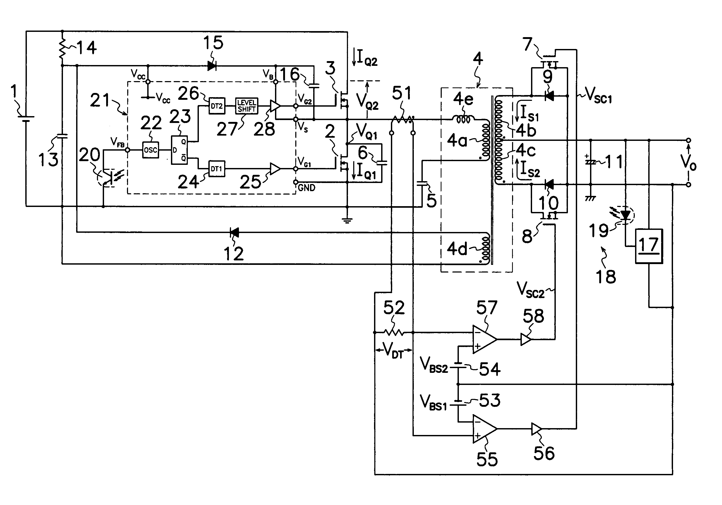
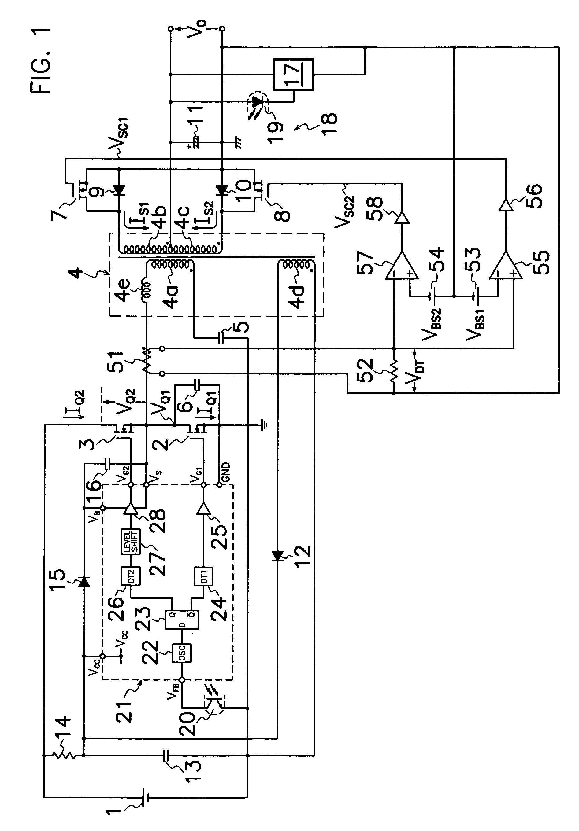
[0033] As shown in FIG. 1, the DC-DC converter of synchronous rectification type according to the present invention, comprises a current detection transformer 51 as current detecting means for detecting electric currents IQ1, IQ2 flowing through primary side circuit of a transformer 4; a current detecting resistor 52 for converting electric current detected by detection transformer 51 into a corresponding voltage VDT; first and second DC bias power supplies 53 and 54 as biasing means for producing bias voltages VBS1 and VBS2 higher than voltage corresponding to excitation current through transformer 4; a first comparator 55 as first comparing means for producing a first synchronous drive pulse signal VSC1 to turn first rectifying MOS-FET 7 on when detection voltage VDT by current detecting resistor 52 to non-inverted input terminal + of first comparator 55 exceeds a bias voltage VBS1 of first DC bias power supply 53 applied to inverted input terminal − of first comparator 55; a firs...

third embodiment

[0043] the DC-DC converter of synchronous rectification type shown in FIG. 8, comprises, in addition to the converter shown in FIG. 4, an operational amplifier 60 as a synchronous signal generator for producing pulse signals VPL synchronously with frequency of voltage produced in secondary winding 4c of transformer 4; and an integration circuit of a resistor 61 and integral capacitor 62 for producing ramp signals VRP whose inclination is inverted every half cycle of pulse signal VPL from operational amplifier 60 wherein a junction of resistor 61 and integral capacitor 62 is connected to a reference potential side (the left end in FIG. 8) of current detecting resistor 52. Inverted and non-inverted input terminals − and + of operational amplifier 60 are connected respectively to secondary winding 4c of transformer 4 and ground in secondary side circuit. In operation, operational amplifier 60 produces rectangular pulse signals VPL of the alternating polarity shown in FIG. 9(B) with fre...


PUM


Abstract

A DC-DC converter of synchronous rectification type is provided which comprises: a current detector (51) for discerning electric current (IQ1, IQ2) flowing through a primary side circuit; first and second DC biasing power supplies (53, 54) for producing a bias voltage (VBS1, VBS2) higher than voltage corresponding to excitation current through transformer (4); and first and second comparators (55, 57) for activating first and second rectifying MOS-FET (7, 8) when current detector (51) produces the detection voltage (VDT) over bias voltage (VBS1, VBS2) of first and second DC biasing power supplies (53, 54). As each of first and second rectifying MOS-FETs (7, 8) in secondary side circuit is driven synchronously with electric current (IQ1, IQ2) flowing through the primary side circuit except excitation current component through transformer (4), the converter can minimize switching loss in each rectifying MOS-FET (7, 8) in secondary side circuit to improve conversion efficiency.

Description

TECHNICAL FIELD [0001] This invention relates to a DC-DC converter of synchronous rectification type which can improve the conversion efficiency by reduction in switching loss in a secondary side circuit of the converter. BACKGROUND OF THE INVENTION [0002] A DC-DC converter of synchronous rectification type is known as a switching power source device of high conversion efficiency which comprises a transformer, primary and secondary side circuits of the transformer. The primary side circuit comprises at least one main switching element and a primary winding of the transformer connected in series with a DC power source. The secondary side circuit comprises a secondary winding of the transformer electromagnetically coupled to the primary winding, and at least one rectifying switching element connected between the secondary winding and a load. The main switching element is turned on and off during the switching operation, and the rectifying switching element is driven synchronously with...

Claims


Application Information

Patent Timeline
IPC IPC(8): H02M3/335H02M3/337
CPCH02M3/33507Y02B70/1475H02M3/337H02M3/33592Y02B70/10H02M3/33571H02M3/01
Inventor USUI, HIROSHIFURUKOSHI, RYUICHIFUKUMOTO, YUKINARI
Owner SANKEN ELECTRIC CO LTD
Why Eureka
Try Eureka