Airflow generating structure and the apparatus thereof

a technology of airflow and generating structure, which is applied in the direction of machines/engines, stators, liquid fuel engines, etc., can solve the problems of increasing noise and vibration, shortening the service life, etc., and achieves the effect of reducing noise, reducing noise, and increasing rotational velocities

Inactive Publication Date: 2007-01-11
RISUN EXPANSE
View PDF7 Cites 12 Cited by
  • Summary
  • Abstract
  • Description
  • Claims
  • Application Information

AI Technical Summary

Benefits of technology

[0009] As previously discussed, the conventional axial-flow fan has the drawbacks of a lower flow rate, causing more noise and greater vibrations at higher rotational velocities, and a shorter service life due to vibration of the blades. As for the radial-flow fan, the structure thereof forces the airflow to change the path of flow abruptly, posing more resistance t

Problems solved by technology

As previously discussed, the conventional axial-flow fan has the drawbacks of a lower flow rate, causing more noise

Method used


Image

  • Airflow generating structure and the apparatus thereof
  • Airflow generating structure and the apparatus thereof
  • Airflow generating structure and the apparatus thereof

Examples


first embodiment

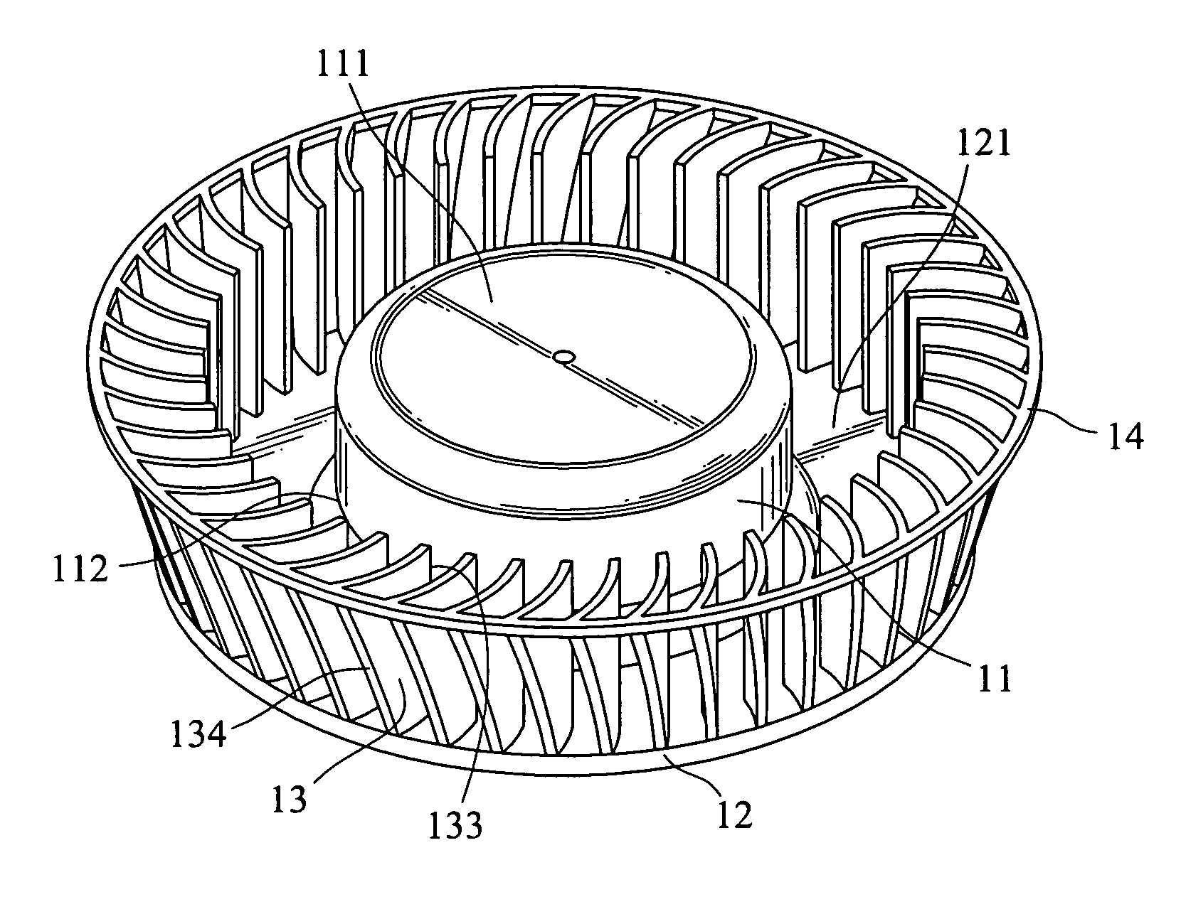
[0030] Referring to FIGS. 5 and 6 for the invention, the airflow generating structure 10 includes a hub 11, a holding section 12, a plurality of spoilers 13 and a stabilization ring 14.

[0031] The hub 11 has a top end 111 and a bottom end 112. The top end 111 is substantially formed in a convex shape. The bottom end 112 has a concave portion 113 to hold a spindle 15 protruding outwards.

[0032] The holding section 12 is substantially an annular plate integrally formed on the periphery of the bottom end 112, and is extended outwards from the hub 11, and has a holding surface 121 on one side, facing upwards.

[0033] Each of the spoilers 13 has a convex surface and a concave surface to form a curved profile. Each spoiler 13 has a root 131 and a tip 132, and has a height approximated to that of the hub 11. The root 131 is fastened to the holding section 12. The spoilers 13 are located round the periphery of the holding section 12 in an equally-spaced manner. The tip 132 is remote from the ...

second embodiment

[0046] Refer to FIG. 11 for the invention that provides an airflow generating structure 40 with an improved air channeling effect. It includes a hub 41, a holding section 42, a plurality of spoilers 43 and a stabilization ring 44 that are largely like those previously discussed. The main distinction of the two is that there is a round angle 45 formed between the juncture of the holding section 42 and the hub 41. Hence when the airflow passes rapidly from the upper side of the hub 41 towards the holding section 42, the round angle 45 can channel the airflow smoothly to the periphery of the holding section 42 and discharge the airflow through the lower side of the hub 41, to avoid directly hitting the holding section 42. Hence kinetic energy loss of air can be reduced, and the flow rate and dynamic pressure can be maintained without dropping too much.

[0047] Refer to FIG. 12 for a third embodiment of the invention that provides an airflow generating structure 50 with an improved air ch...


PUM


Abstract

An airflow generating structure and the apparatus thereof includes a hub, a holding section extended outwards from one end of the hub, and a plurality of spoilers located on the periphery of the holding section in the axial direction that are spaced from one another. Each of the spoilers has two curved surfaces and an outer edge inclined outwards so that the area that all the tips of the spoilers enclose is larger than that of the holding section. Air is sucked in through one end of the hub remote from the holding section and flows towards the other end, and is discharged through the periphery of the holding section.

Description

FIELD OF THE INVENTION [0001] The present invention relates to a fan and particularly to an airflow generating structure and the apparatus thereof with less operational noise and a higher flow rate. BACKGROUND OF THE INVENTION [0002] A fan mainly aims to discharge airflow and result in forced convection. In general a fan draws air in a direction parallel with the spindle axis of the impeller and drives the air through the blades. The airflow direction depends on the geometric structure of the impeller. Refer to FIGS. 1A through 1C for the geometric structure of an impeller. According to the relative directions of intake and discharge airflow, a fan can be classified in one of the three types: axial-flow fan 1, radial-flow fan 2 and diagonal-flow fan 3. [0003] Referring to FIGS. 1A and 2, the directions of intake and discharge airflow of the axial-flow fan 1 are the same. The axial-flow fan 1 has the advantages of a simple structure and lower fabrication cost. Hence it is widely used...

Claims


Application Information

Patent Timeline
IPC IPC(8): F04D29/44
CPCF04D29/281
Inventor HUANG, CHIANG-CHENGSUN, CHIEN-CHUNG
Owner RISUN EXPANSE
Why Eureka
Try Eureka