Fuel cell

a fuel cell and cell surface technology, applied in the field of fuel cells, can solve the problems of fuel cell inability to be used in a variety of applications, flow field shape cannot be freely designed, etc., and achieve the effect of uniform temperature distribution on the electrode surface and simple structur

Inactive Publication Date: 2007-01-11
HONDA MOTOR CO LTD
View PDF8 Cites 20 Cited by
  • Summary
  • Abstract
  • Description
  • Claims
  • Application Information

AI Technical Summary

Benefits of technology

[0011] A main object of the present invention is to provide a fuel cell having a simple structure in which the flow direction of a reactant gas is substantially perpendicular to the flow direction of a coolant, and uniform temperature distribution in electrode surfaces of the fuel cell is achieved.
[0020] Further, according to the present invention, in the coolant connection channel, the flow rate of the coolant supplied to the area near the inlet of the reactant gas flow field is larger than the flow rate of the coolant supplied to the other area. Therefore, in the reactant gas flow field, a large amount of coolant is supplied to the area near the inlet of the reactant gas flow field. Accordingly, it is possible to reliably cool the area near the inlet of the reactant gas flow field where the power generation reaction occurs actively, and it is possible to suppress the increase in the temperature of the electrodes. Accordingly, the increase in the electrical resistance is suppressed effectively, and the power generation is performed efficiently.

Problems solved by technology

That is, the shapes of the flow fields cannot be designed freely.
In such a structure, the fuel cell cannot be used in a variety of applications.

Method used


Image

  • Fuel cell
  • Fuel cell
  • Fuel cell

Examples


first embodiment

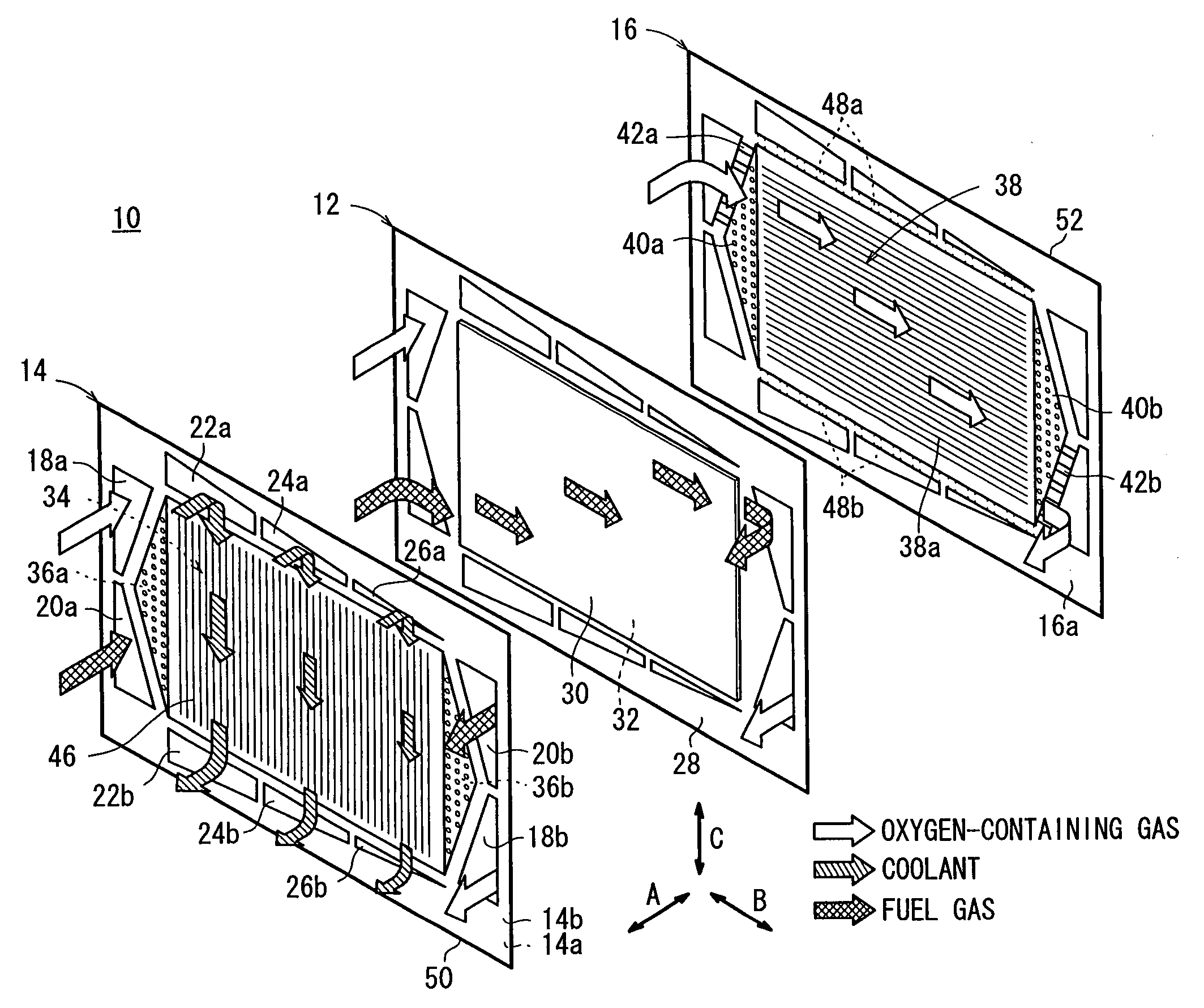
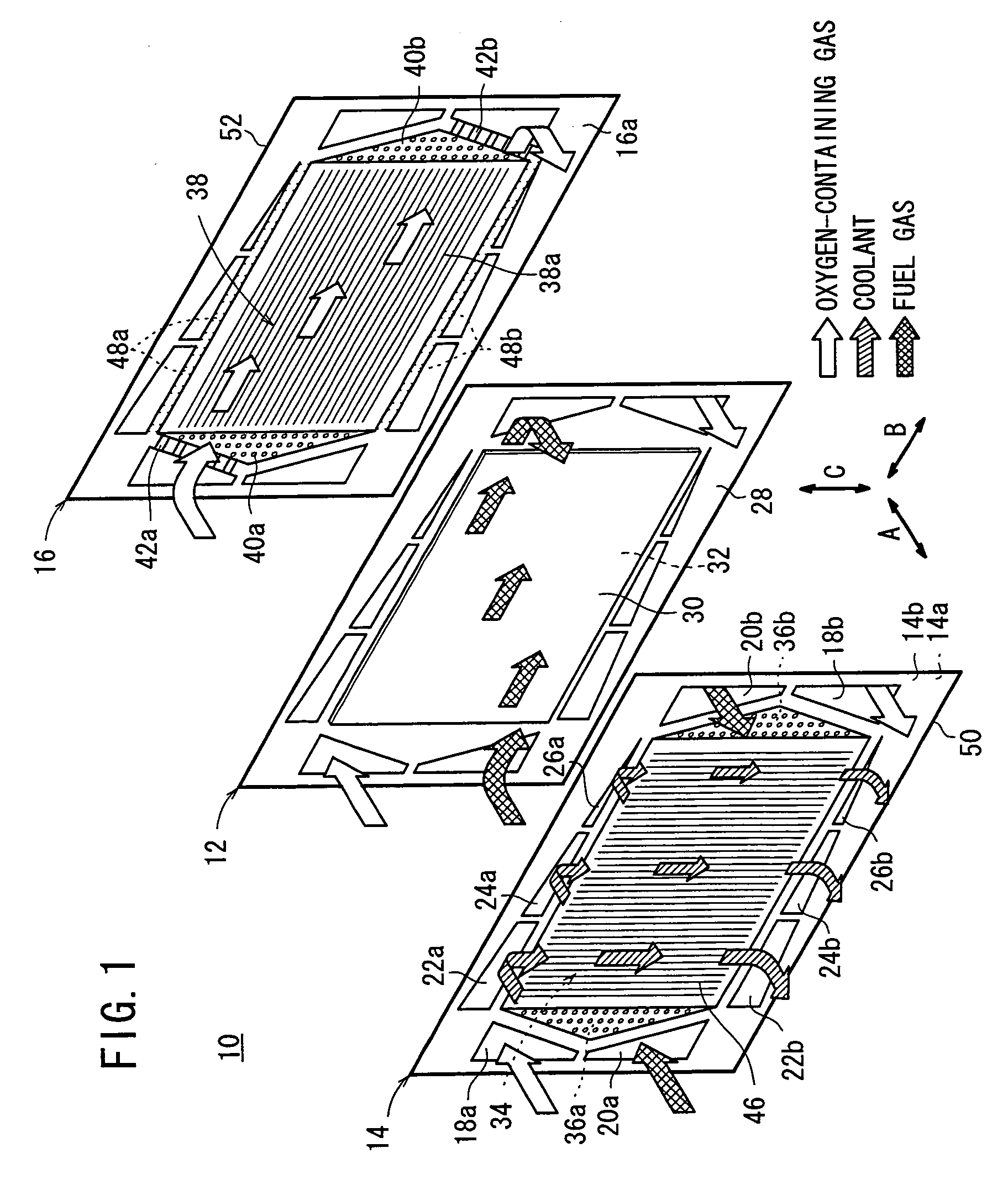
[0032]FIG. 1 is an exploded perspective view showing main components of a fuel cell 10 according to the present invention. In general, a plurality of the fuel cells 10 are stacked together in a horizontal direction to form a fuel cell stack.

[0033] Each of the fuel cells 10 includes a membrane electrode assembly (electrolyte electrode assembly) 12 and an anode side metal separator 14 and a cathode side metal separator 16 sandwiching the membrane electrode assembly 12. For example, the anode side metal separator 14 and the cathode side metal separator 16 are steel plates, stainless steel plates, aluminum plates, or plated steel sheets. The anode side metal separator 14 and the cathode side metal separator 16 may be made of metal plates having anti-corrosive surfaces formed by surface treatment.

[0034] At one end of the fuel cell 10 in a longitudinal direction indicated by an arrow B in FIG. 1, an oxygen-containing gas supply passage 18a for supplying an oxygen-containing gas, and a fu...

second embodiment

[0064] In the second embodiment, the number of the inlet connection grooves 78a connected to the coolant supply passage 72a is the smallest, and the number of the outlet connection grooves 78b connected to the coolant discharge passage 72b is the smallest. Therefore, the flow rate of the coolant supplied to an area near the outlets of the fuel gas flow field 34 and the oxygen-containing gas flow field 38 is smaller than the flow rate of the coolant supplied to the other area.

[0065] Further, the number of the inlet connection grooves 74a connected to the coolant supply passage 68a is the largest, and the number of the outlet connection grooves 74b connected to the coolant discharge passage 68b is the largest. The flow rate of the coolant supplied to an area near the inlets of the fuel gas flow field 34 and the oxygen-containing gas flow field 38 is larger than the flow rate of the coolant supplied to the other area. Thus, the same advantages as in the case of the first embodiment can...

third embodiment

[0066]FIG. 6 is a front view showing a cathode side metal separator 80 of a fuel cell according to the present invention.

[0067] In effect, the cathode side metal separator 80 has the structure corresponding to combination of the first and second embodiments. The coolant connection channel includes the coolant supply passages 22a, 24a, 26a and the coolant discharge passages 22b, 24b, and 26b. The cross sectional areas of the openings of the coolant supply passages 22a, 24a, 26a, and the coolant discharge passages 22b, 24b, and 26b are different depending on the position in the width direction. Further, the coolant connection channel includes the inlet connection grooves 74a, 76a, and 78a, and the outlet connection grooves 74b, 76b, and 78b. The intervals of the inlet connection grooves 74a, 76a, and 78a, and the outlet connection grooves 74b, 76b, and 78b are different depending on the position in the width direction.

[0068] Thus, in the third embodiment, the same advantages as in th...


PUM

PropertyMeasurementUnit
widthaaaaaaaaaa
flow rateaaaaaaaaaa
areaaaaaaaaaaa

Abstract

A fuel cell includes a membrane electrode assembly and an anode side metal separator and a cathode side metal separator sandwiching the membrane electrode assembly. An oxygen-containing gas flows in an oxygen-containing gas flow field in a horizontal direction. A coolant flows in a coolant flow field in a vertical direction. The coolant flow field is connected to coolant supply passages and coolant discharge passages. The opening of one of the coolant supply passages and the opening of one of the coolant discharge passages are smaller than those of the other coolant supply passages and the other coolant discharge passages in cross section, respectively. Thus, the flow rate of the coolant supplied to an area near outlets of the oxygen-containing gas flow field and the fuel gas flow field become smaller than the flow rate of the coolant supplied to the other area.

Description

BACKGROUND OF THE INVENTION [0001] 1. Field of the Invention [0002] The present invention relates to a fuel cell formed by stacking electrolyte electrode assemblies and separators alternately in a horizontal direction. Each of the electrolyte electrode assemblies includes a pair of electrodes and an electrolyte interposed between the electrodes. A reactant gas flow field for supplying a reactant gas is formed between the electrode electrolyte assembly and one of separators sandwiching the electrolyte electrode assembly for supplying a reactant gas along a surface of the electrode, and a coolant flow field is formed between adjacent separators which are stacked together for allowing a coolant to flow in a direction substantially perpendicular to the flow direction of the reactant gas. [0003] 2. Description of the Related Art [0004] For example, a polymer electrolyte fuel cell employs a membrane electrode assembly (MEA) which includes an anode, a cathode, and an electrolyte membrane (...

Claims


Application Information

Patent Timeline
Patent Type & Authority Applications(United States)
IPC IPC(8): H01M8/04H01M2/02H01M2/14
CPCH01M8/0206H01M8/0267Y02E60/50H01M8/2465H01M8/04029H01M8/2483H01M8/0271H01M8/241
Inventor MOHRI, MASAHIRONAGOSHI, KENTAROODA, MASARU
Owner HONDA MOTOR CO LTD
Why Eureka
Try Eureka