

Engine control apparatus
- Summary
- Abstract
- Description
- Claims
- Application Information
AI Technical Summary
Benefits of technology
Problems solved by technology
Method used
Image

Examples
Embodiment Construction
[0026] While the claims are not limited to the illustrated embodiments, an appreciation of various aspects of the apparatus is best gained through a discussion of at least one example thereof.
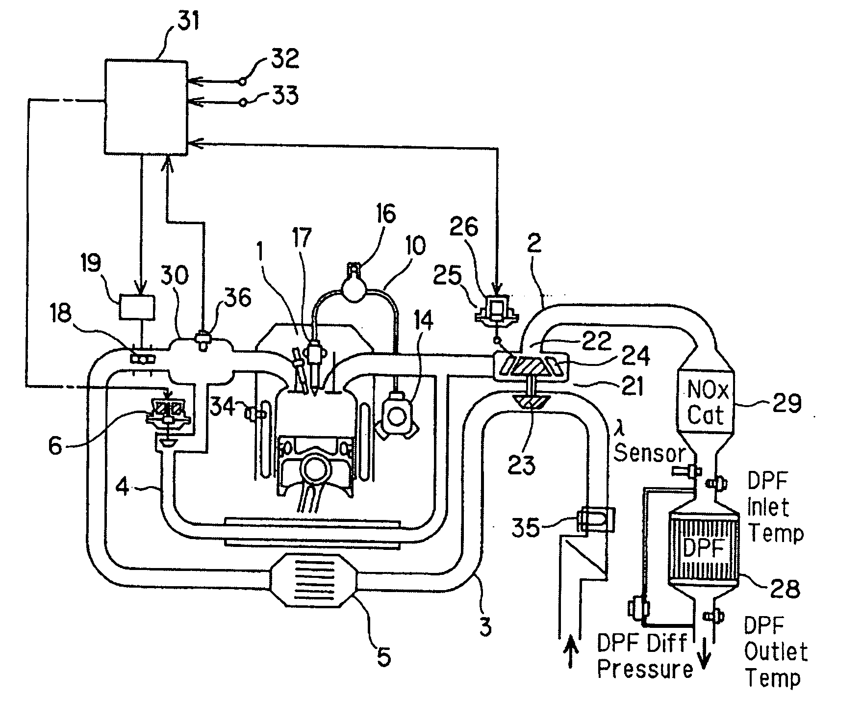
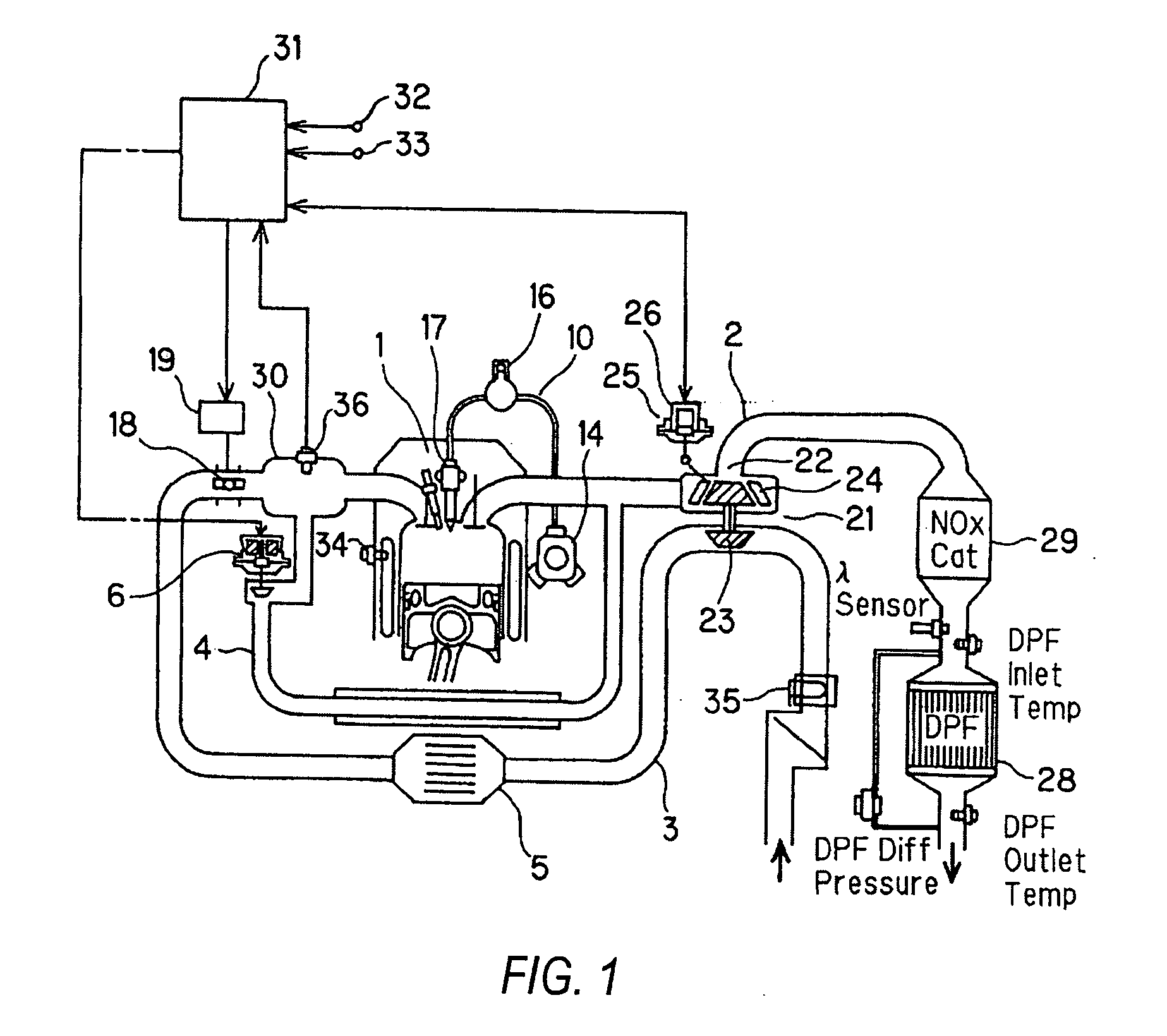
[0027]FIG. 1 is a schematic view of an embodiment of an engine. The engine 1 is provided with an exhaust path 2 and an inlet path 3. An EGR path 4 interconnects the exhaust path 2 and the inlet path 3. An intercooler 5 cools high temperature intake air compressed by a compressor of a turbo-supercharger, described below.
[0028] The EGR path 4 is provided with a diaphragm-type EGR valve 6 that operates in response to control pressure from a pressure control valve (not shown). The pressure control valve is driven by a duty control signal from an engine controller 31, whereby the predetermined EGR rate is obtained according to the driving conditions.
[0029] The engine 1 is provided with a common rail-type fuel injection device 10 as a fuel supplying means or mechanism. This fuel injection device 1...
PUM
 Abstract
Description
Claims
Application Information