
Systems and methods for integrated plasma processing of waste

a waste plasma and waste technology, applied in the direction of machines/engines, combustion types, lighting and heating apparatuses, etc., can solve the problems of reducing the supply of fossil fuels,

Active Publication Date: 2007-01-18
MARTIN ROBERT C JR +3
View PDF15 Cites 9 Cited by
  • Summary
  • Abstract
  • Description
  • Claims
  • Application Information

AI Technical Summary

Problems solved by technology

First, the combustion of fossil fuels can create harmful solid and gaseous emissions that must be filtered and controlled to prevent pollution.
Second, the solid emissions, such as fly ash, that are filtered from the output of the fossil fuel combustion processes must be deposited into waste facilities, such as landfills.
Third, supplies of fossil fuels, such as coal, are finite and will eventually be depleted.
As these energy sources are naturally occurring, the by-products associated with their conversion are more limited.
These naturally occurring energy sources, however, are somewhat limited in their potential total capacity, especially in view of the rapidly increasing demand for energy.
While widely used, incineration facilities are costly, ineffective, and sources of pollution.
Additionally, like fossil fuel power plants, incineration facilities generate a significant amount of solid emission by-product in the form of fly ash.
Plasma waste processing facilities are complex systems that differ significantly from combustion type processing facilities.
In addition, by virtue of the fact that a plasma arc torch uses only a small quantity of gas to support the arc and generate the heat, combustion is unlikely to occur spontaneously in the materials which are being heated.
Despite the overwhelmingly exciting theoretical benefits, the implementation of plasma waste processing facilities and systems in practical environments have been extremely limited due to implementation obstacles and to the deficiencies of the prior art systems.
The difficultly in achieving efficient and cost effective implementations of plasma waste processing facilities is perhaps best illustrated by the fact that despite their tremendous possible benefits, there are only two known commercial plasma waste processing facilities in the world, all located in Japan.
The implementation of plasma waste processing facilities has been significantly hindered by many factors.
One primary hindrance is due to the relatively large capital cost associated with the initial provisioning of a plasma waste processing facility.
The construction and provisioning of the multiple complex elements of a plasma waste processing facility, including the plasma reactor, gas treatment systems, and the electrical generator systems, require a significant amount of initial investment.
For example, a smaller facility with a relatively small daily volume of MSW will inherently be less efficient than a larger facility with a relatively large daily volume of MSW.
Furthermore, some plasma reactor configurations are less well suited for energy recovery due to the relatively high plasma energy requirements (500 to 600 kWhr / ton of waste) of certain types of arc plasma torches.

Method used


Image

  • Systems and methods for integrated plasma processing of waste
  • Systems and methods for integrated plasma processing of waste
  • Systems and methods for integrated plasma processing of waste

Examples


Embodiment Construction

[0031] To facilitate an understanding of the principles and features of the invention, it is explained hereinafter with reference to its implementation in illustrative embodiments. In particular, the present invention is directed toward systems and methods for integrated plasma waste processing.

[0032] Referring now to the figures, wherein like reference numerals represent like parts throughout the several views, exemplary embodiments of the present invention will be described in detail. Throughout this description, various components may be identified having specific values, these values are provided as exemplary embodiments and should not be limiting of various concepts of the present invention as many comparable sizes and / or values may be implemented.

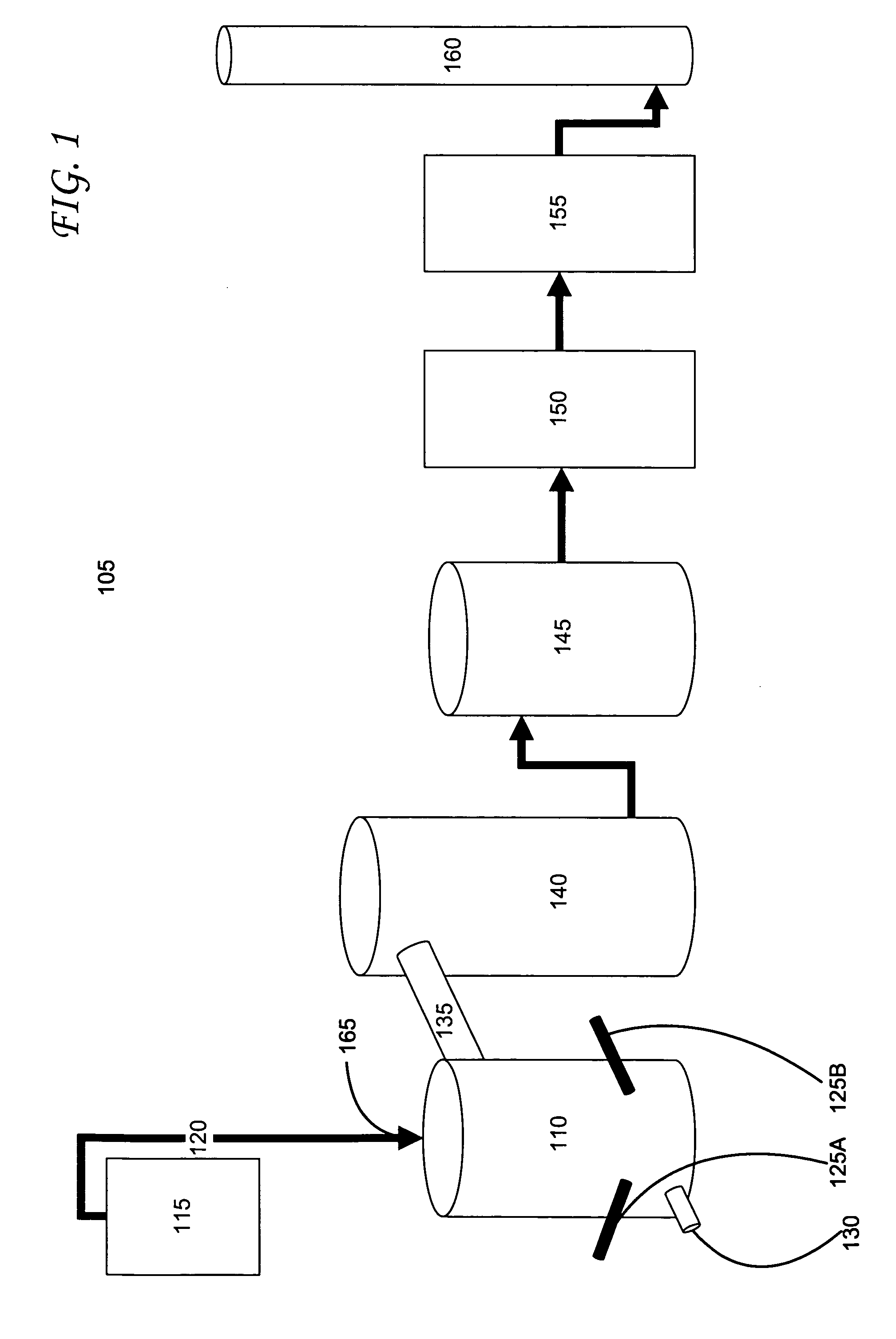
[0033]FIG. 1 is an illustration of a prior art plasma waste processing system. The various stages of a plasma waste processing system 105 are shown throughout FIG. 1. The plasma waste processing system 105 has a plasma reactor 110 i...


PUM


Abstract

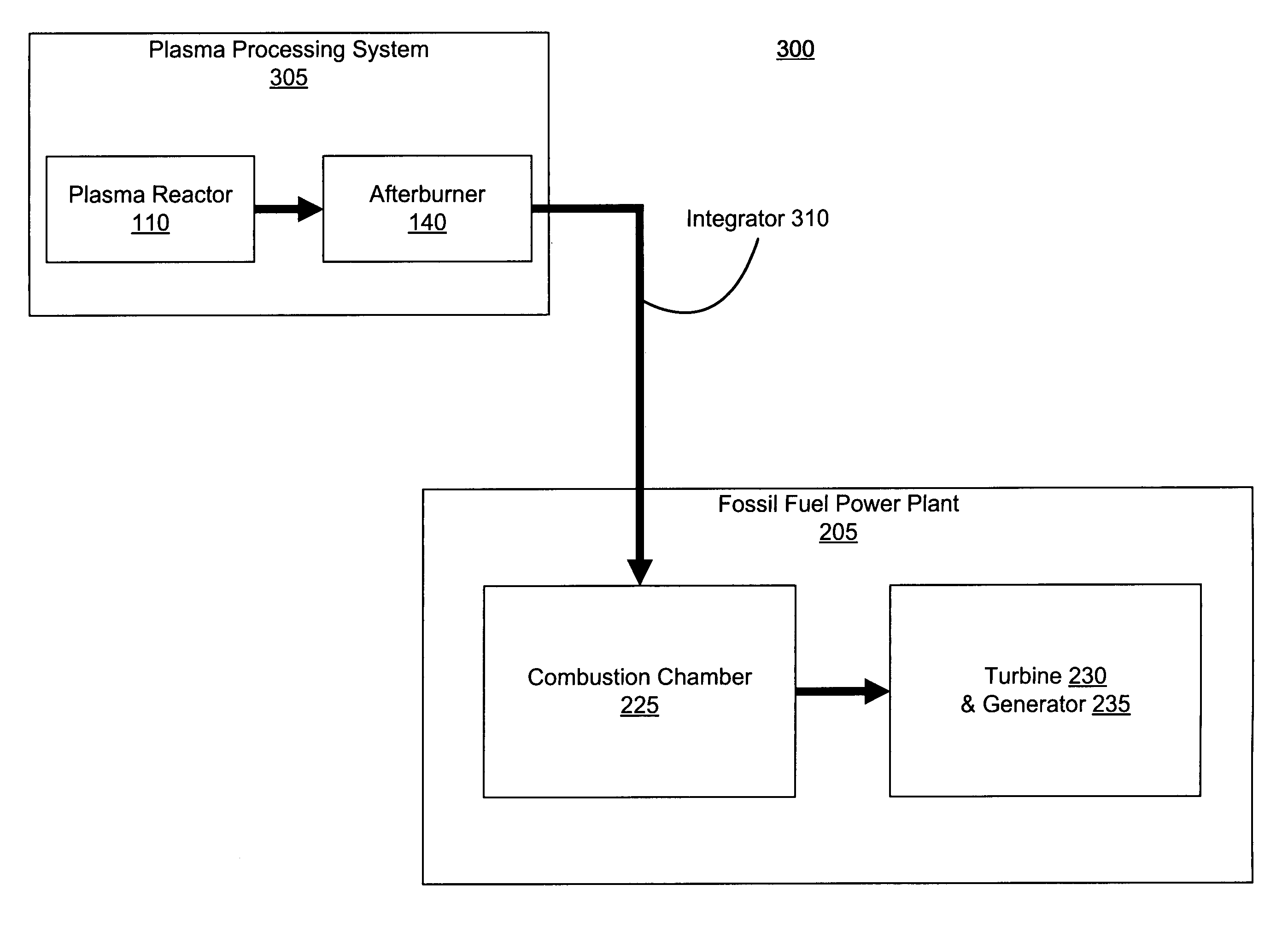
Systems and methods of integrating plasma waste processing are described. An integreted energy generation system provided with a fossil fuel power plant system having a combustion chamber and a plasma waste processing system having an output. The integrated energy generation system also including an integrator for combining the output of thermal energy from the plasma waste processing system with the combustion chamber of the fossil fuel power plant.

Description

CROSS REFERENCE TO RELATED APPLICATIONS [0001] This application claims priority of U.S. Provisional Patent Application No. 60 / 693,400, filed Jun. 23, 2005, the entire contents and substance of which are hereby incorporated by reference.BACKGROUND [0002] 1. Field of the Invention [0003] The present invention relates to energy generation and, more particularly, to energy generation through the plasma treatment of waste materials. [0004] 2. Description of Related Art [0005] In 1800, the world population totaled less than 1 billion. In the mere two hundred years between 1800 and 2000, the world population exploded by six times to a total of 6.1 billion inhabitants. Predictions estimate that this number could rise to near 9 billion in the next fifty years. As the population grows exponentially, two corollaries grow along with it: (1) the demand for energy, and (2) the creation of waste. The processes used to create the energy necessary to meet the ever increasing energy demands of the wo...

Claims


Application Information

Patent Timeline
Patent Type & Authority Applications(United States)
IPC IPC(8): F23B30/00F23G5/00
CPCF02C3/20F02C3/28F23G5/006F23G5/085Y02T50/671F23G2201/40F23G2204/201F23G2206/203Y02E20/12F23G5/16Y02T50/60
Inventor SMITH, MICHAEL S.CARAVATI, KEVIN C.CIRCEO, LOUIS J.MARTIN, ROBERT C. JR.
Owner MARTIN ROBERT C JR
Learn More