
Air cleaner in all terrain vehicle

an air cleaner and all terrain technology, applied in the direction of cycle equipment, instruments, separation processes, etc., can solve the problem of difficult to accurately measure and achieve the effect of improving control performance and accurately measuring the temperature of air introduced into the engin

Active Publication Date: 2007-01-18
HONDA MOTOR CO LTD
View PDF7 Cites 31 Cited by
  • Summary
  • Abstract
  • Description
  • Claims
  • Application Information

AI Technical Summary

Benefits of technology

[0008] For solving the above-mentioned problems it is an object of the present invention to provide an air cleaner in an all terrain vehicle which air cleaner can be formed in a simple manner while improving the control performance for effecting optimal combustion of an engine by accurately measuring the temperature of air introduced into the engine.
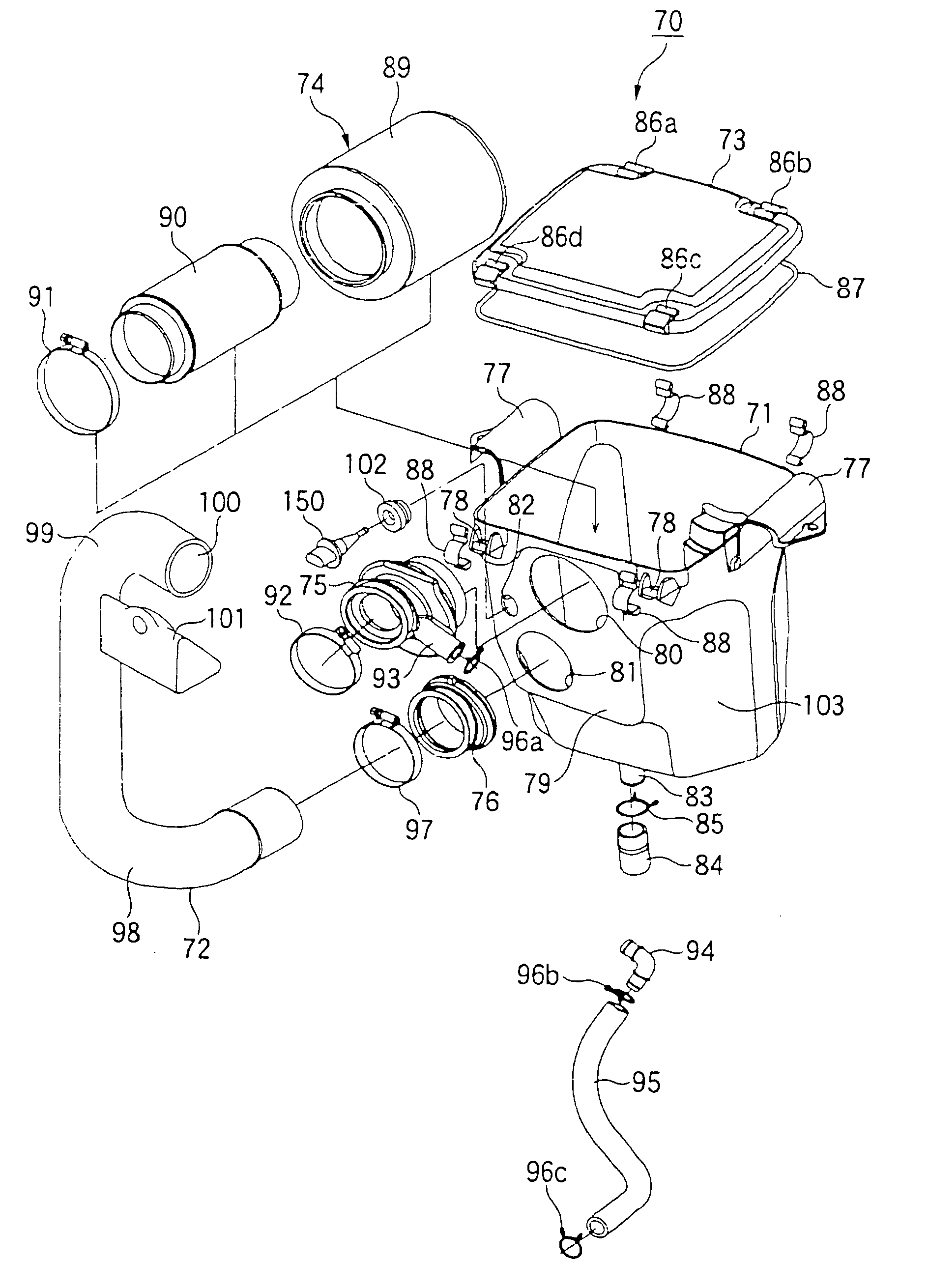
[0013] According to the first aspect of the present invention, since the temperature sensor for measuring the temperature of air introduced into the engine is disposed in either the front or rear of the air cleaner case which is disposed behind the engine, it is possible to measure the temperature of air without being influenced by radiant heat from the engine. Consequently, in comparison with an air cleaner wherein the temperature sensor is disposed in a side portion of the air cleaner case, it is not necessary to ensure a temperature sensor mounting space between the side portion of the air cleaner case and a frame to support the side portion, so that not only it is possible to ensure a sufficient capacity of the air cleaner case, but also the control performance for effecting optimal combustion of the engine can be improved by accurately measuring the temperature of air introduced into the engine with use of the temperature sensor.
[0014] According to the second aspect of the present invention, since the temperature sensor is disposed on the other side of the exhaust pipe with respect to the longitudinal center line of the air cleaner case and hence can be positioned away from the exhaust pipe, the temperature sensor becomes difficult to be influenced by a high temperature of the exhaust pipe, whereby an erroneous measurement of the temperature sensor caused by the heat of the exhaust pipe is prevented and it is possible to measure the intake air temperature accurately.
[0015] According to the third aspect of the present invention, since the first mounting hole for fixing the connecting tube, the second mounting hole for fixing the snorkel duct which is for introducing air into the air cleaner case, and the third mounting hole for fixing the temperature sensor, are formed in either the front or the rear, the first, second and third mounting holes can be formed in either the front or the rear of the air cleaner case simultaneously in the same process. For that reason, it is possible to make a subsequent step or the like unnecessary and improve the productivity.
[0016] According to the fourth aspect of the present invention, since the temperature sensor for measuring the temperature of air introduced into the engine is disposed in the connecting tube for connecting the air cleaner case and the throttle valve with each other, the air temperature can be measured without being influenced by radiant heat of the engine, so that the control performance for effecting optimal combustion of the engine can be improved by accurately measuring the temperature of air introduced into the engine with use of the temperature sensor. Moreover, in case of attaching the temperature sensor to the air cleaner case, since the air cleaner case is made of resin, it is necessary to mount the temperature sensor through an elastic member, with a consequent increase in the number of parts. However, since the connecting tube also serves as the elastic member, the temperature sensor can be attached directly to the connecting tube and hence it is possible to decrease the number of parts.

Problems solved by technology

However, in the case where the temperature measuring means and the engine are adjacent to each other, the temperature of the temperature measuring means itself may be increased by radiant heat from the engine, thus making it difficult to measure an accurate temperature of air introduced into the engine.

Method used


Image

  • Air cleaner in all terrain vehicle
  • Air cleaner in all terrain vehicle
  • Air cleaner in all terrain vehicle

Examples


first embodiment

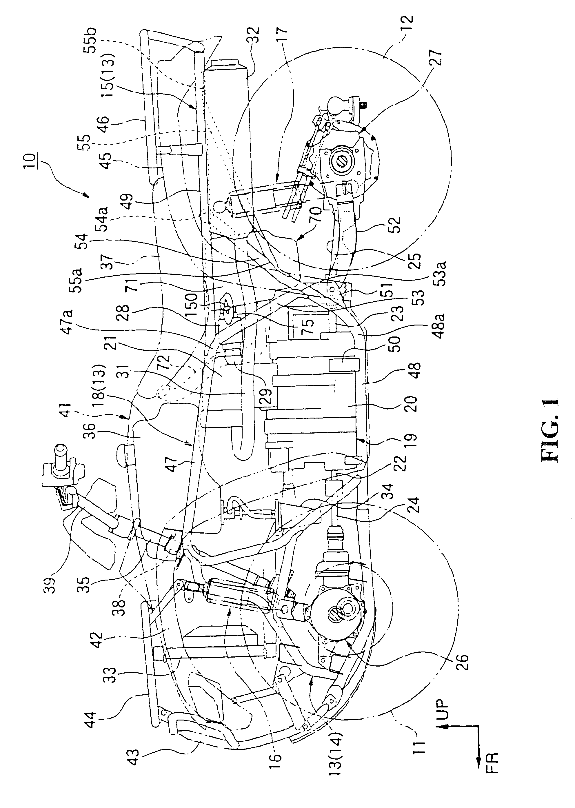
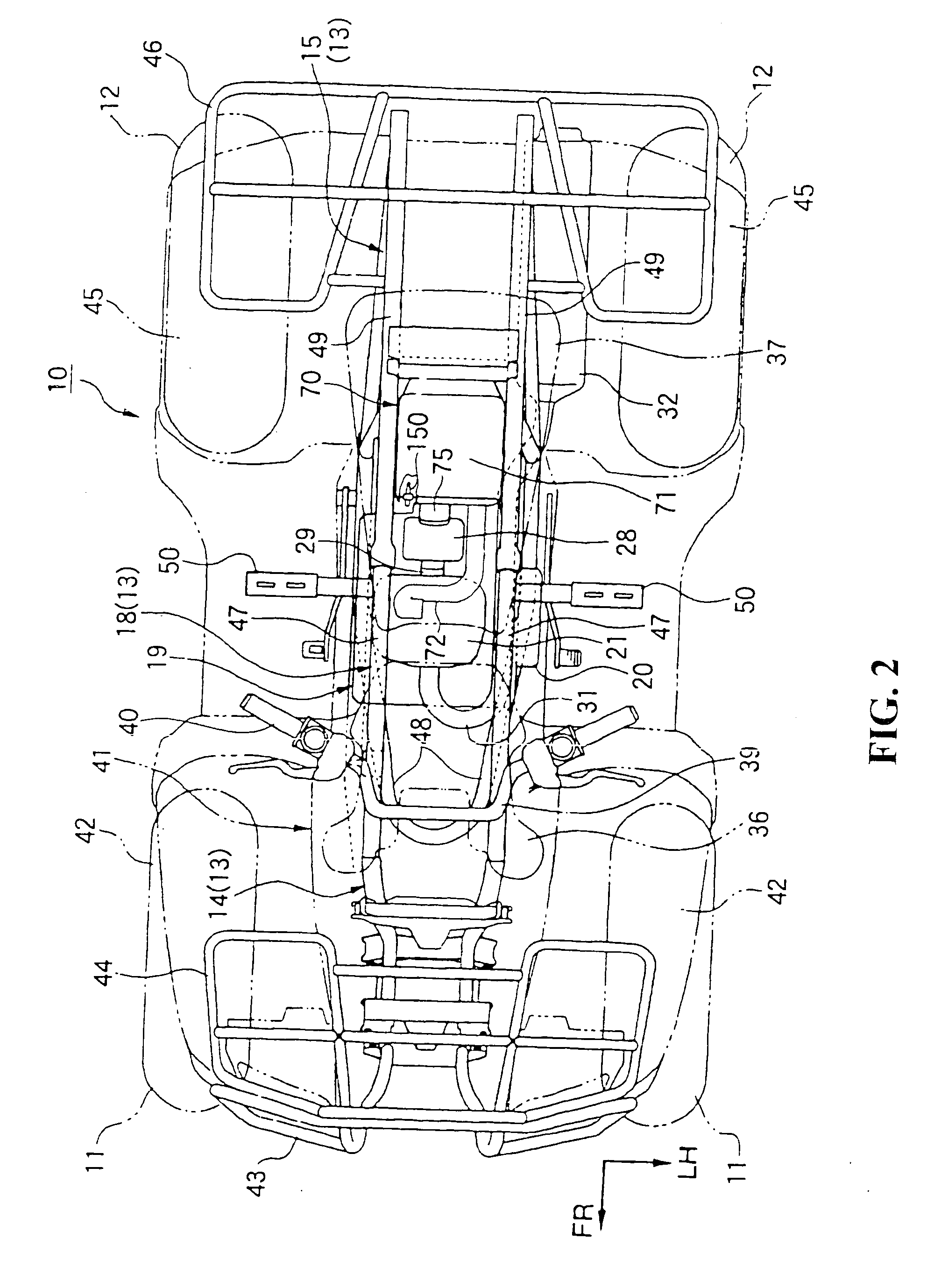
[0028] FIGS. 1 to 5 illustrate the present invention.

[0029] The front and rear wheels 11, 12 are low pressure balloon tires of a relatively large diameter and are disposed on front and rear sides, respectively, of a vehicle body which is constituted as a small-sized and light-weight body. With the front and rear wheels 11, 12, a minimum road clearance is ensured large to improve the running-through performance mainly on rough roads. Each front wheel 11 and each rear wheel 12 are suspended through a front suspension 16 and a rear suspension 17, respectively, in a front frame 14 and a rear frame 15 as constituents of a body frame 13.

[0030] A center frame 18 is disposed nearly centrally of the body frame 13 and an engine 19 as a prime mover is mounted on the center frame 18. The engine 19 is, for example, a water-cooled type single-cylinder reciprocating engine and is disposed longitudinally with a rotational axis of a crank shaft extending in the longitudinal direction of the vehicle...


PUM

PropertyMeasurementUnit
temperatureaaaaaaaaaa
diameteraaaaaaaaaa
pressureaaaaaaaaaa

Abstract

An air cleaner is provided in an all terrain vehicle in order to improve the control performance for effecting optimal combustion in an engine by accurately measuring the temperature of air introduced into the engine. The air cleaner includes an air cleaner case disposed behind an engine, a throttle valve disposed between the engine and the air cleaner case, and connecting tube for connecting the air cleaner case and the throttle valve with each other. A temperature sensor is disposed in either a front or rear face of the air cleaner case. Optionally, the temperature sensor is disposed in the connecting tube.

Description

CROSS-REFERENCE TO RELATED APPLICATION [0001] The present application claims priority under 35 U.S.C. §119 to Japanese Patent Application No. 2005-183794, filed Jun. 23, 2005, the entire contents of which are hereby incorporated by reference. BACKGROUND OF THE INVENTION [0002] 1. Field of the Invention [0003] The present invention relates to an air cleaner in an all terrain vehicle for running on rough roads such as a four-wheel buggy. [0004] 2. Description of Background Art [0005] With the recent tendency to an electronic control in vehicles there has been developed a technique wherein the temperature of air introduced into an engine is measured and the amount of air to be introduced at a low or high temperature is adjusted to effect appropriate combustion (see, for example, Japanese Patent Laid-Open No. 2001-349242). [0006] More particularly, there has been proposed a technique wherein temperature measuring means for measuring the temperature of air introduced into an engine is at...

Claims


Application Information

Patent Timeline
Patent Type & Authority Applications(United States)
IPC IPC(8): F02M35/10G01M19/00F02M35/02B62J99/00B62K5/00B62K5/01F02M35/16G01M99/00
CPCF02M35/0203F02M35/024F02M35/10013F02M35/162F02M35/1038F02M35/16F02M35/10144
Inventor KAWATANI, SHINJI
Owner HONDA MOTOR CO LTD
Learn More