
Dual hybrid propulsion system

a hybrid propulsion and hybrid technology, applied in the direction of propulsion parts, propulsion using engine-driven generators, transportation and packaging, etc., can solve the problem of not being able to meet the high energy demand and permit an adequate charging level, so as to achieve high energy demand, increase fuel economy, and similar highway fuel economy

Inactive Publication Date: 2007-01-18
JONES STEVEN MARK
View PDF14 Cites 18 Cited by
  • Summary
  • Abstract
  • Description
  • Claims
  • Application Information

AI Technical Summary

Benefits of technology

[0011] Due to the inherent, but separate, advantages of both the series and the parallel drives, the above embodiments enables the dual series hybrid vehicle to provide increased fuel economy compared to conventional series hybrid systems. The dual hybrid invention allows a series hybrid configuration to achieve similar highway fuel economy when compared to conventional parallel hybrid designs. This arrangement eliminates the main disadvantage of conventional parallel hybrid designs as used in a vehicle. It has been found that at slow speed, such as stop and go urban driving, the parallel system will allow the main storage battery pack to deplete its energy below a comfortable and usable level of charge. A series hybrid system is more adaptable to urban driving because it constantly funnels limited amounts of electrical energy back into the system's first electrical storage device.
[0012] The main negative of a series hybrid system is that it does not permit an adequate charging level to sustain the high energy demand associated with long term, high speed driving. The above-embodiments of the present invention prevent depletion of the first electrical storage device by using two liquid fueled engines and generators to power the first electrical storage device. In addition, the control of the operation of the drive motor is more versatile and overall efficient.

Problems solved by technology

The main negative of a series hybrid system is that it does not permit an adequate charging level to sustain the high energy demand associated with long term, high speed driving.

Method used


Image

  • Dual hybrid propulsion system
  • Dual hybrid propulsion system
  • Dual hybrid propulsion system

Examples


Embodiment Construction

[0017] This invention operates as follows:

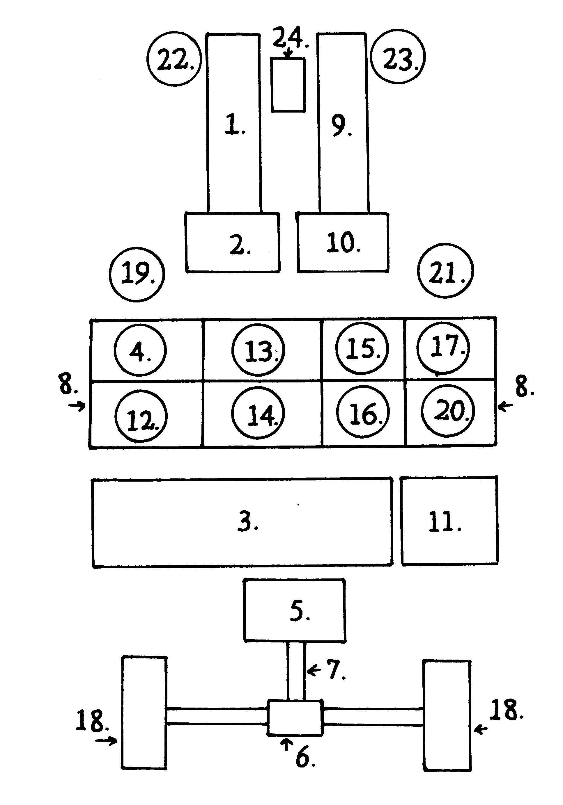
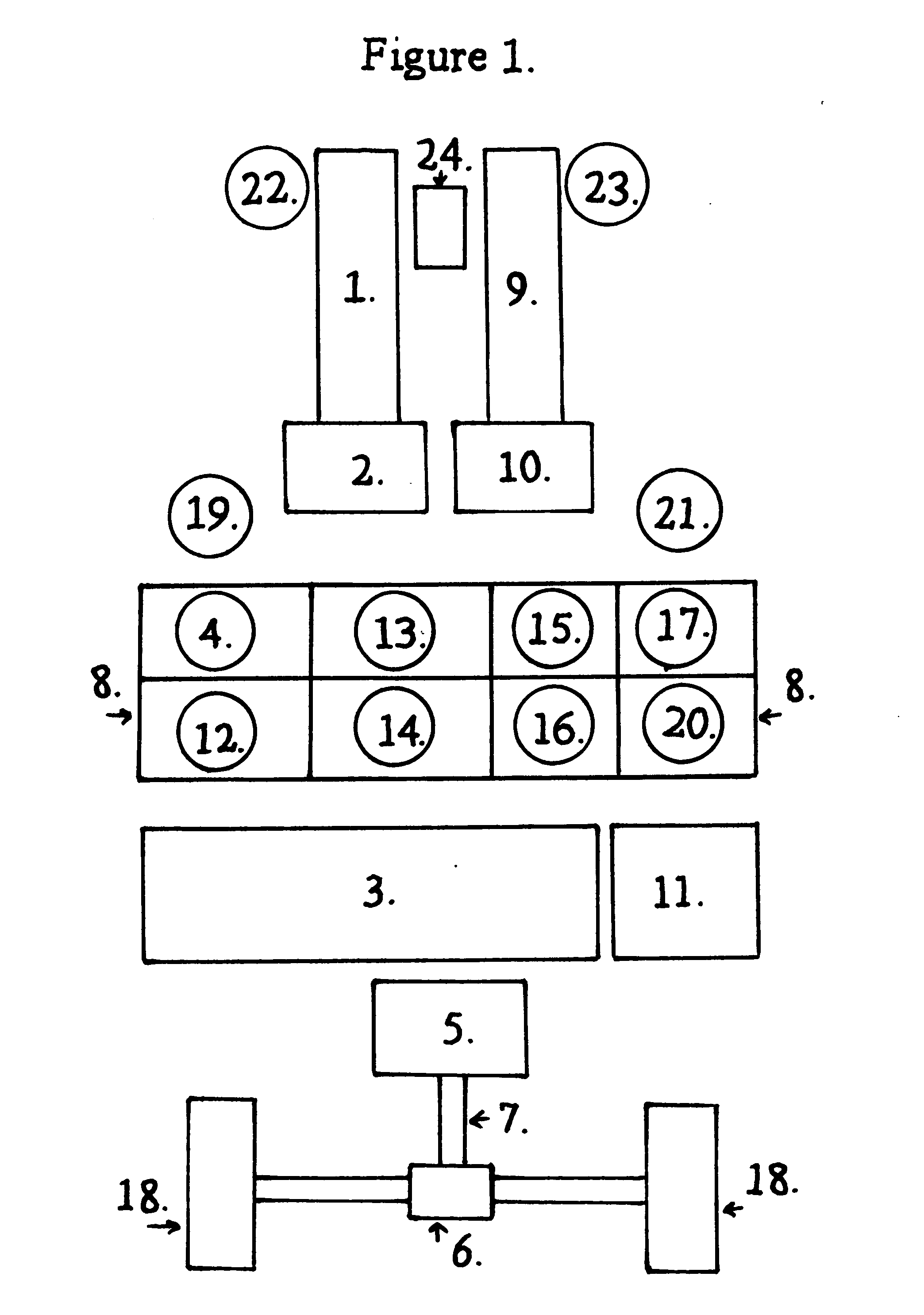
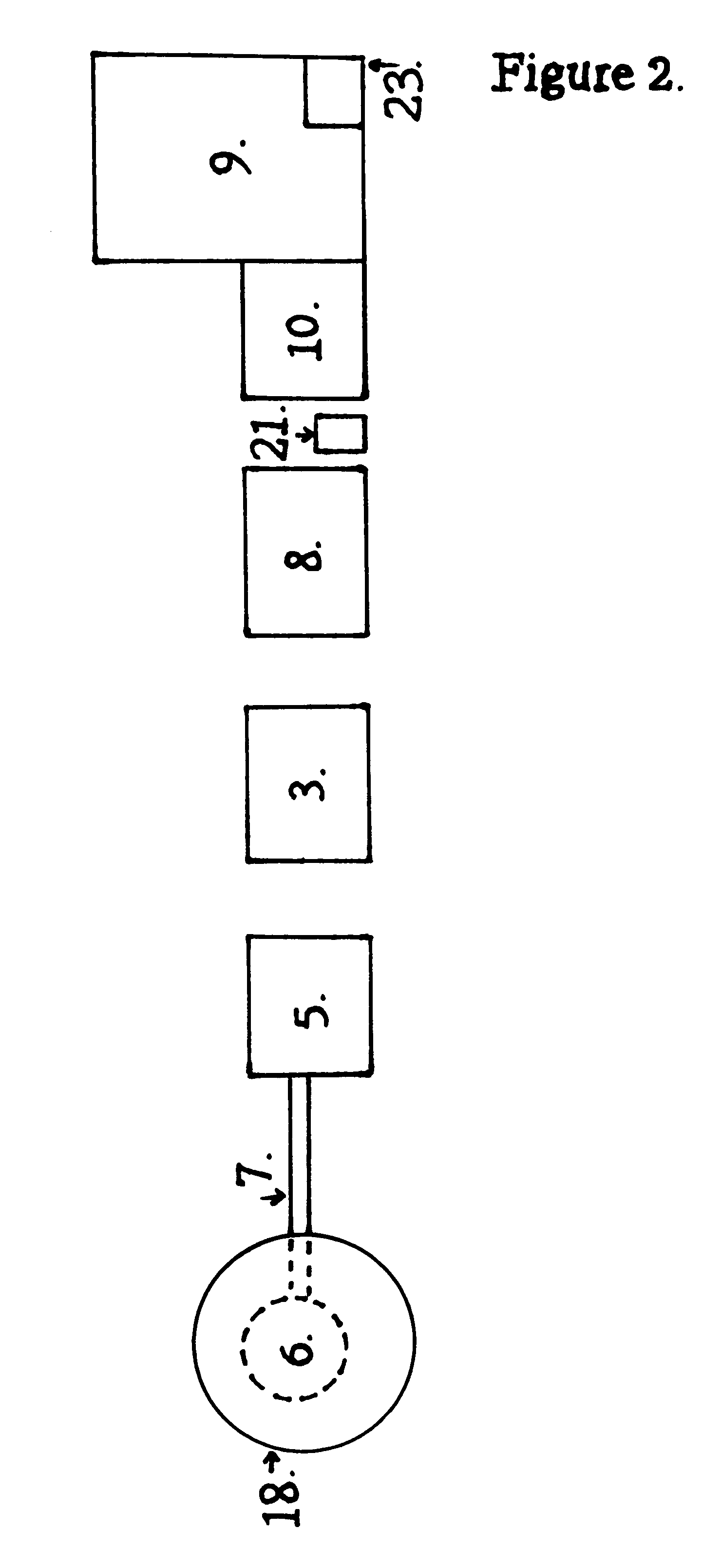
[0018] The Dual Hybrid Propulsion System operates as a series hybrid electric vehicle. When operating in stop and go traffic the vehicle can be powered solely by the first electrical storage device. when fully charged, producing a zero tailpipe emission mode. When the first electrical storage device is drained to a predetermined level one of the two liquid fueled engines will be automatically started by the process controllers and operate the liquid fueled engines will operate at the peak torque curve RPM to recharge them. Once up to full charge the process controller will automatically shutdown the liquid fueled engine until the next time the batteries are depleted to the predetermined level, then the cycle will start again. This provides the highest fuel economy for this driving condition. When rapid acceleration is required, the throttle position sensor sends a signal to the main control panel and the process controller which starts one ...


PUM


Abstract

With the growing demand of oil products in the world, this invention can help curb the fuel consumption rate of trucks / large motor vehicles without reducing peak power outputs. A vehicle having a “dual series” hybrid power systems includes two liquid fueled internal combustion engines, each engine having a generator directly connected. There is an electric motor for drivability directly connected to one or more ground engaging wheels. A first electrical storage device (battery pack) stores electricity that powers the electric motor. Two voltage reducers are coupled between both of the generators and the first electrical storage device and has an accessory voltage output, which has a lower voltage than the charging power output of the generators, to keep the accessory second electrical storage device fully charged.

Description

BACKGROUND OF THE INVENTION [0001] This invention relates to electric hybrid vehicles. There are basically three types of electric propulsion systems known for vehicles. [0002] First, there is a pure electric drive vehicle. The pure electric drive vehicle has an electric motor which receives power from a main battery pack via a controller. The controller controls the speed of the electric motor. [0003] The major disadvantage of a pure electric drive vehicle is that the range is very limited and the vehicle must be stopped and connected to an energy source such as an electrical outlet in order to be recharged. [0004] The second type of electric propulsion system for vehicles is a series hybrid system. There are three major components in a series system: (1) a generator; (2) an electric motor arranged in series; and (3) an engine powering the generator. Mechanical energy generated by the engine is converted to electrical energy by the generator and is then converted back to mechanical...

Claims


Application Information

Patent Timeline
IPC IPC(8): B60L8/00
CPCY02T10/7077B60L11/12B60L50/15Y02T10/7072Y02T10/70
Inventor JONES, STEVEN MARK
Owner JONES STEVEN MARK
Learn More