Solid oxide fuel cell

a fuel cell and solid oxide technology, applied in the direction of cell components, electrochemical generators, chemistry apparatuses and processes, etc., can solve the problems of premature decrease of the power generation performance of the power generating cell, corresponding reduction of the efficiency of the power generating system, and reduction of the cell performance, so as to achieve efficient and stable power generation and excellent reforming capability

Inactive Publication Date: 2007-01-18
MITSUBISHI MATERIALS CORP +1
View PDF8 Cites 49 Cited by
  • Summary
  • Abstract
  • Description
  • Claims
  • Application Information

AI Technical Summary

Benefits of technology

[0045] According to the fourth aspect of the present invention, since, with the reforming catalyst layer disposed between the separator and the fuel-electrode current collector, the reforming catalyst obstructing the fuel gas flow through the fuel gas flow path is not present, the gas flow path having invariably good flowing in the fuel cell stack can be secured without being influenced by loading amount of the hydrocarbon reforming catalyst, resulting in the efficient and stable power generation with the internal reforming.
[0046] Besides, since the hydrocarbon reforming catalyst is disposed in a place, where the temperature is highest in the fuel cell stack, between t

Problems solved by technology

Since reforming reaction is an endothermic one, the method needs to supply heat at a high temperature for reforming reaction to the external reformer and needs a wasteful energy to obtain the high temperature heat, and has a problem that the power generating system efficiency is correspondingly reduced.
However, the conventional solid oxide fuel cells which employ the internal reforming method described above have problems that the endothermic reaction generates an inhomogeneous temperature distribution in the power generating cells, and the thermal stress due to that causes degradation and breakage of the power generating cells, and the local temperature decrease causes reduction of the cell performance.
Besides, the conventional solid oxide fuel cells which employ the internal reforming method described above have problems that Ni in the fuel-electrode layer is degraded under the influence of CO gas formed in the reforming process and H2S gas and the like formed from sulfur contained in the raw fuel in reforming, and carbon deposited from the raw fuel is adhered to Ni in the fuel-electrode layer, thereby causing premature decrease in the power generating performance of the power generating cell.
The high-temperature operating type can easily obtain a high temperature required for reforming, but such low-temperature oper

Method used


Image

  • Solid oxide fuel cell
  • Solid oxide fuel cell
  • Solid oxide fuel cell

Examples


first embodiment

A First Embodiment

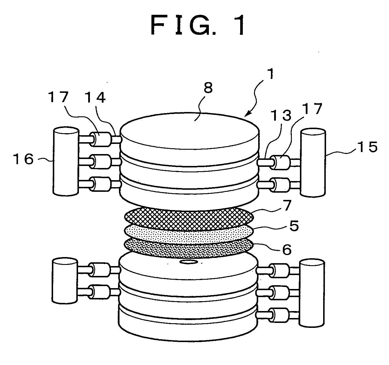
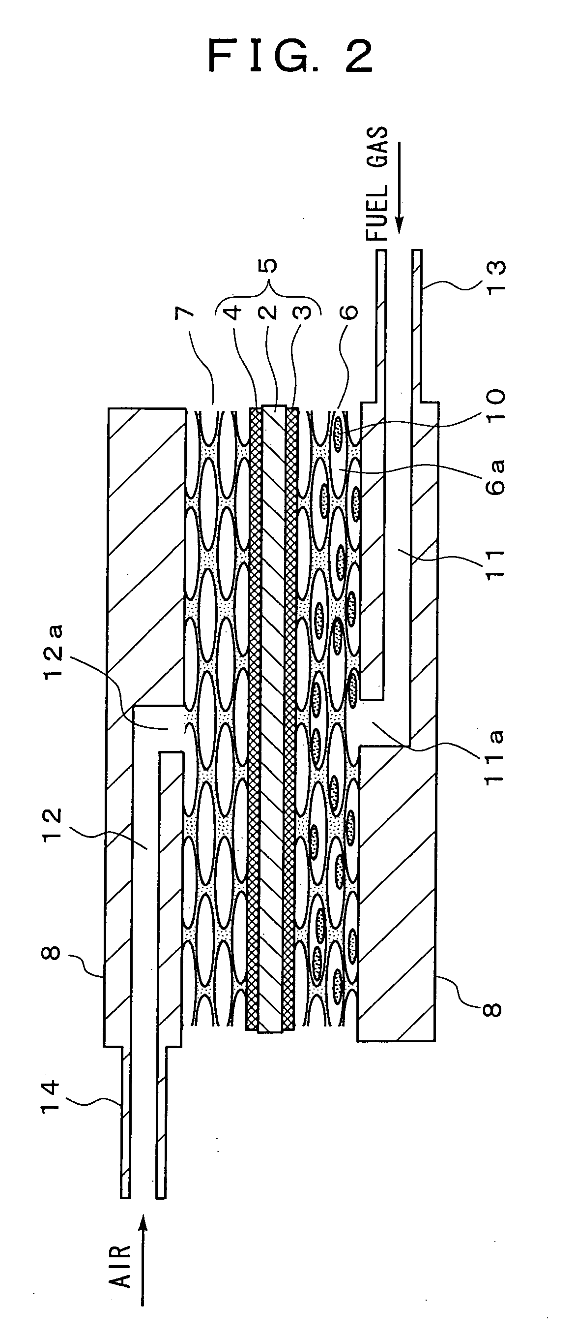
[0060] A first embodiment of a solid oxide fuel cell of a flat-plate stacking type according to the present invention will be illustrated. FIG. 1 is an exploded perspective view showing a fuel cell stack construction. FIG. 2 to FIG. 4 are sectional views showing essential parts of fuel cell stacks different from each other.

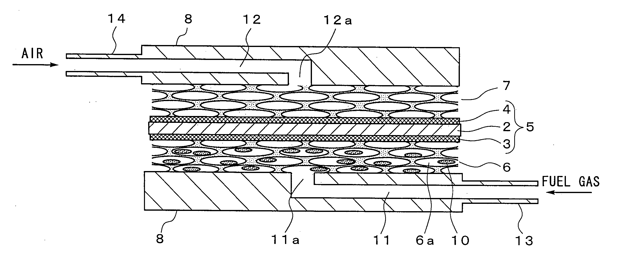
[0061] As shown in FIG. 1 to FIG. 4, a fuel cell stack 1 (hereinafter, referred to simply as stack 1) has a structure in which a power generating cell 5 disposing a fuel-electrode layer 3 and a air-electrode layer 4 on both surfaces of a solid electrolyte layer 2, an fuel-electrode-side porous metal 6, an air-electrode-side porous metal 7, and separators 8 on the outer sides of the porous metals 6 and 7, respectively, are stacked in the order.

[0062] The solid electrolyte layer 2 is composed of a stabilized zirconia doped with yttria (YSZ), etc.; the fuel-electrode layer 3 a metal of Ni, etc. or a cermet of Ni-YSZ, etc.; the air-electrode layer ...

second embodiment

A Second Embodiment

[0085] Now, a second embodiment of a solid oxide fuel cell according to the present invention will be illustrated. In the embodiment, the same reference numerals are given for the same components as in the first embodiment described above, and their explanation is simplified.

[0086] A fuel cell stack 1 of the embodiment, as shown in FIG. 5, has a structure in which a fuel-electrode current collector 21 and an air-electrode current collector 22 are disposed on both sides of a power generating cell 5, and separators 8 are disposed on the outer sides of the current collectors 21 and 22.

[0087] A power generating cell 5 has, as shown in the first embodiment described above, a lamination structure in which a solid electrolyte layer 2 is interposed between an air-electrode layer 4 and a fuel-electrode layer 3. The solid electrolyte layer 2 is composed of a stabilized zirconia doped with yttrium (YSZ), etc. and the air-electrode layer 4 is composed of LaMnO3, LaCoO3, etc...

third embodiment

A Third Embodiment

[0099] A third embodiment of a solid oxide fuel cell according to the present invention will be now illustrated. In the embodiment, the same reference numerals are given for the same components as in the embodiments described above to simplify the description thereof.

[0100] In the third embodiment, as shown in FIG. 7 and FIG. 8 as in the second embodiment described above, a stack unit is constructed of a power generating cell 5 in which a fuel-electrode layer 3 and an air-electrode layer 4 are disposed on both surfaces of a solid electrolyte layer 2, a fuel-electrode current collector 31 disposed on the outer side of the fuel-electrode layer 3, an air-electrode current collector 32 disposed on the outer side of the air-electrode layer 4, and separators 8 disposed on the outer sides of the current collectors 31 and 32, respectively, a plurality of the stack units being stacked into a cylindrical fuel cell stack 1.

[0101] The solid electrolyte layer 2 is composed of...


PUM


Abstract

An object of the present invention is to provide a solid oxide fuel cell assembled with an internal reforming mechanism stable and efficient over a long period. To achieve the object, in the present invention, a fuel-electrode layer 3 and an air-electrode layer 4 are disposed on both surfaces of a solid electrolyte layer 2; a fuel-electrode-side porous metal 6 and an air-electrode-side porous metal 7 are disposed on the outer surfaces of the fuel-electrode layer 3 and the air-electrode layer 4, respectively; and a separator 8 is disposed on each of the outer surfaces of the fuel-electrode-side porous metal 6 and the air-electrode-side porous metal 7. Then, the solid oxide fuel cell is constructed by closely adhering them all. The pores 6a in the fuel-electrode-side porous metal 6 is partially or fully filled with a hydrocarbon reforming catalyst 10, and reforming reaction is driven by the reforming catalyst 10 before a fuel gas reaches the fuel-electrode layer 3.

Description

BACKGROUND OF THE INVENTION [0001] 1. Field of the Invention [0002] The present invention relates to solid oxide fuel cells having a structure in which a porous metal is interposed between a separator and an electrode layer and more particularly to an internal reforming mechanism of solid oxide fuel cells. [0003] 2. Description of the Related Art [0004] The solid oxide fuel cell (SOFC) is being developed as a third-generation fuel cell for power generation. For such solid oxide fuel cells, three types of tubular, monolithic and planar designs are now proposed, any of which has a laminate structure in which a solid electrolyte composed of an oxide ionic conductor is interposed between an air-electrode layer (cathode) and a fuel electrode layer (anode). Power generating cells composed of the laminate, and separators are stacked alternately by a plurality of numbers, with a fuel-electrode current collector or an air-electrode current collector correspondingly interposed therebetween, t...

Claims


Application Information

Patent Timeline
IPC IPC(8): H01M8/06H01M8/12H01M4/86
CPCC01B3/38C01B2203/0233C01B2203/067C01B2203/1029C01B2203/1058Y02E60/525H01M8/0232H01M8/0637H01M8/243H01M2008/1293Y02E60/50C01B2203/1064H01M8/2432H01M8/2457
Inventor HOSHINO, KOJICHITOSE, NORIHISAYAMADA, TAKASHIKOMADA, NORIKAZUADACHI, KAZUNORIHOSOI, KEI
Owner MITSUBISHI MATERIALS CORP
Why Eureka
Try Eureka