Gas circulating apparatus

Inactive Publication Date: 2007-01-25
DENSO CORP
View PDF8 Cites 65 Cited by
  • Summary
  • Abstract
  • Description
  • Claims
  • Application Information

AI Technical Summary

Benefits of technology

[0013] Accordingly, the heat of the high-temperature exhaust gas introduced from the bypass pipe to the inside of the housing is difficult to be transmitted into the first exhaust gas passage from the second exhaust gas passage. Thus, the heat transmission of the high-temperature exhaust gas to the heat exchanger (first

Problems solved by technology

Accordingly, the heat of the high-temperature exhaust gas introduced from the bypass pipe to the inside of the

Method used


Image

  • Gas circulating apparatus
  • Gas circulating apparatus
  • Gas circulating apparatus

Examples


Embodiment Construction

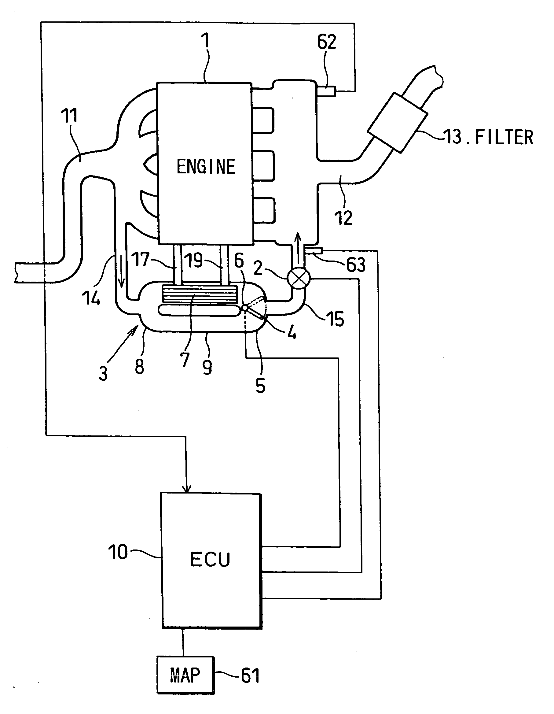
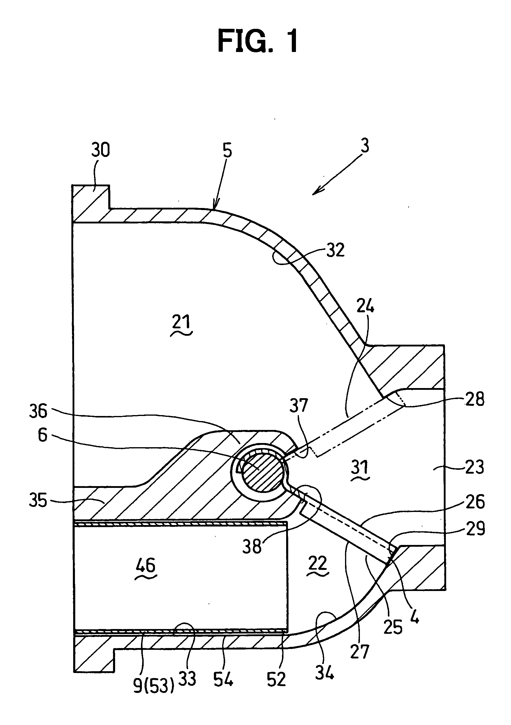
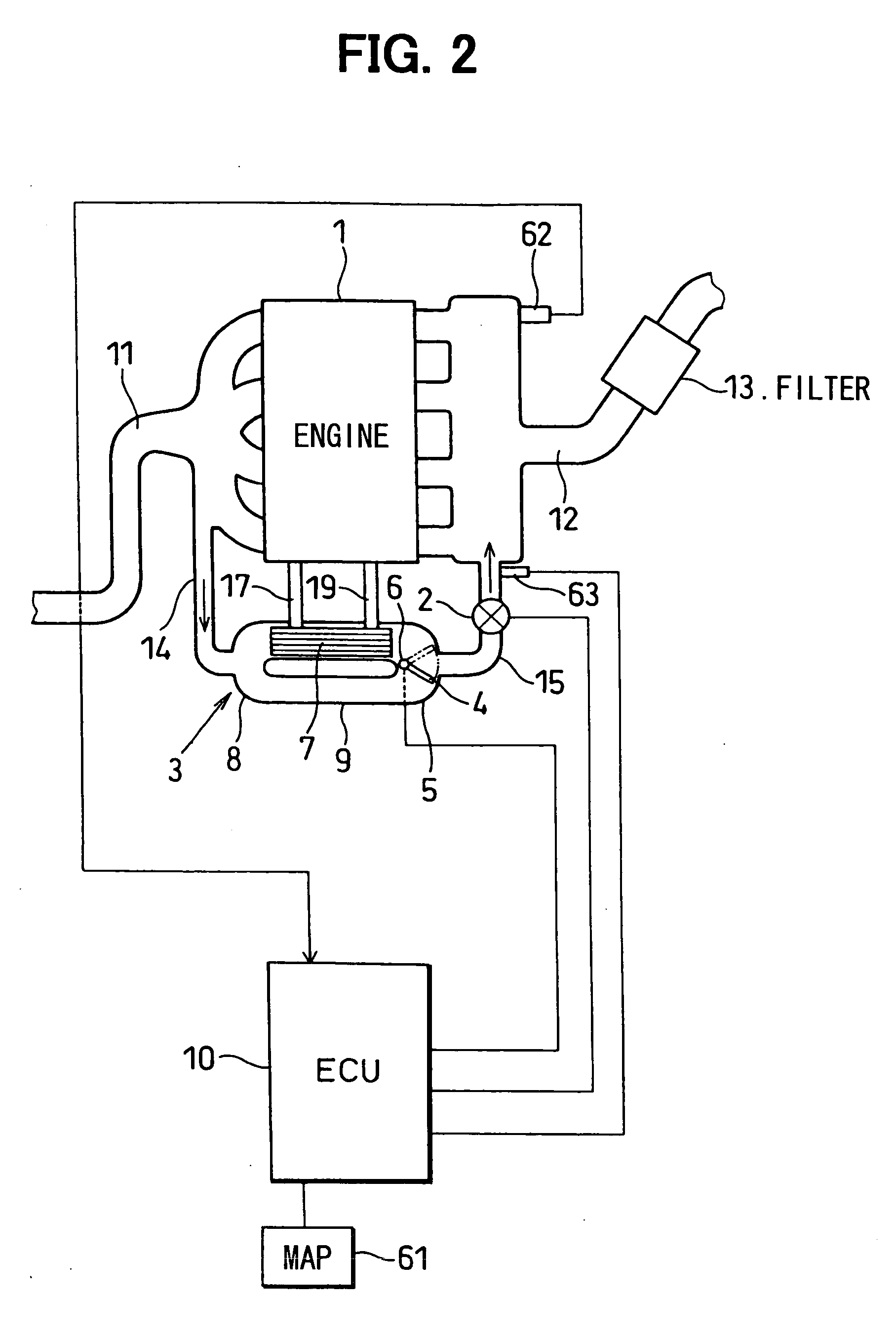
[0019] An embodiment of the present invention will be now described with reference to FIG. 1 and FIG. 3. In this embodiment, a gas circulating apparatus is used for an internal combustion engine 1 (hereinafter referred to as “engine”) e.g., a diesel engine. The gas circulating apparatus is connected to an exhaust passage 11 disposed in the engine 1. The gas circulating apparatus includes a recirculation pipe and an EGR control valve 2. The recirculation pipe is provided to recirculate a portion of an exhaust gas from a combustion room in the engine 1 to an intake passage 12 provided in an intake pipe in the engine 1. The EGR control valve 2 adjusts, continuously or stepwise, the amount of a recirculated exhaust gas (hereinafter referred to as “amount of the EGR”) flowing through the exhaust gas recirculation passage provided in the exhaust gas recirculation pipe. Exhaust gas flows along the exhaust passage 11 in the engine 1. Intake air is filtered by an air cleaner 13 and flows alo...


PUM


Abstract

In a gas circulating apparatus, a bypass pipe extends in parallel with an EGR gas cooler. The aperture end of the bypass pipe is inserted to inside of a housing of a valve device and is positioned adjacent to a valve in the housing. Accordingly, the high-temperature EGR gas heat introduced to a second exhaust gas passage of the housing from the bypass pipe is difficult to be transmitted to a first exhaust gas passage of the housing. Thus, the heat transmission of the high-temperature EGR gas to the EGR gas cooler can be reduced.

Description

CROSS REFERENCE TO RELATED APPLICATION [0001] This application is related to and claims priority from Japanese Patent Application No. 2005-208003 filed on Jul. 19, 2005, the content of which are hereby incorporated by reference. BACKGROUND OF THE INVENTION [0002] 1. Field of the Invention [0003] The present invention relates to a gas circulating apparatus in which a cooling device is provided in an exhaust gas recirculation pipe (EGR pipe) through which a portion of exhaust gas from an internal combustion engine recirculates into an intake side. [0004] 2. Description of Related Art [0005] A conventional gas circulating apparatus includes an EGR pipe for recirculating a portion of an exhaust gas in an internal combustion engine from an exhaust passage to an intake passage, and a water-cooling EGR gas cooler provided in the EGR pipe. The exhaust gas recirculated into the intake passage in the internal combustion engine is cooled in the EGR pipe. The temperature of the exhaust gas is d...

Claims


Application Information

Patent Timeline
IPC IPC(8): F02M25/07
CPCF02M25/0724Y02T10/121F02M25/0754F02M25/0728F02M26/21F02M26/25F02M26/47
Inventor KUROKI, KATSUHIROSHIMANE, OSAMU
Owner DENSO CORP
Why Eureka
Try Eureka