Methods and Apparatus for Completing a Well

Active Publication Date: 2007-01-25
SCHLUMBERGER TECH CORP
View PDF6 Cites 150 Cited by
  • Summary
  • Abstract
  • Description
  • Claims
  • Application Information

AI Technical Summary

Benefits of technology

[0018] The zone or layer of fragmented material separating the casing and the producing formation is designed to prevent the entry of sand an

Problems solved by technology

For example Teplitz fails to limits the propagation of cracks in the cement sheath thus creating the potential of unwanted crossflow between formation layers and loss of zonal

Method used


Image

  • Methods and Apparatus for Completing a Well
  • Methods and Apparatus for Completing a Well
  • Methods and Apparatus for Completing a Well

Examples


Embodiment Construction

AND VARIANTS

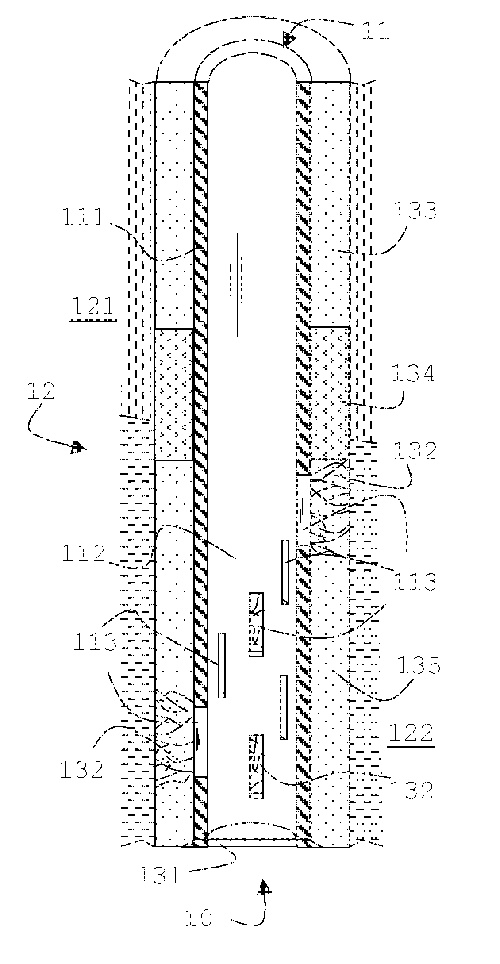
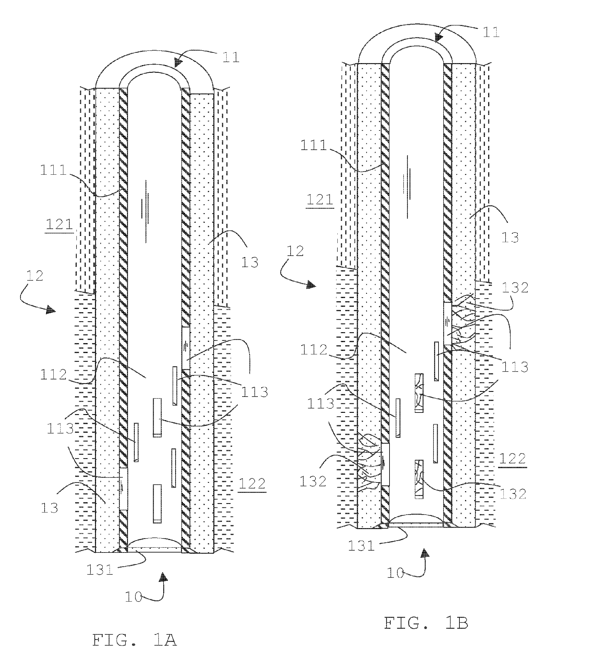
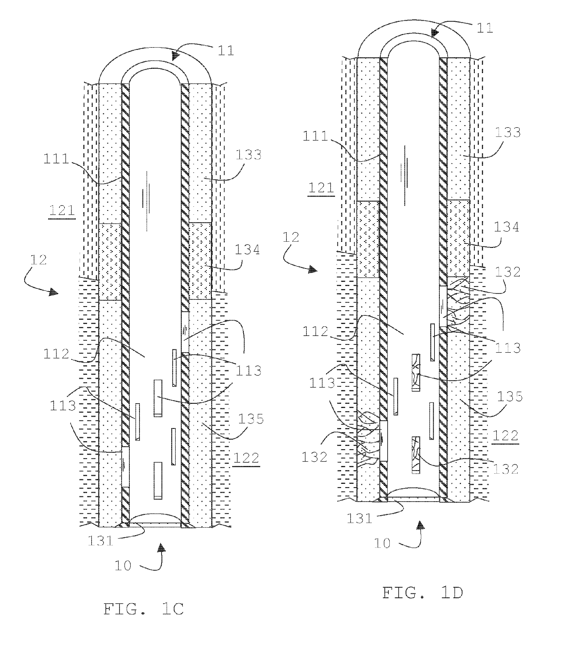
[0032] One aspect of the invention concerns a primary cementing process that will provide a permeable material in front of producing zone. This process may happen in one stage or multiple stages. One embodiment of the invention is shown schematically in FIG. 1A. A casing string 11 is positioned in the well 10, with conventional steel casing 111 in front of the cap rock 121 or impermeable formation, and slotted casing 112 with a plurality of slots 113 in front of a permeable zone 122. A fluid train, comprising a cement slurry appropriate for the wellbore conditions is pumped from the surface along the casing 11 to fill the annulus between the casing 11 and the formation 12 thus forming an impermeable sheath 13 around the well. A cementing plug 131 may also be placed in the fluid train between the fracturable cement slurry and fluids remaining in the casing. This process will leave the hole either free to continue drilling, run tools, or to be filled with oil.

[0033] In FI...


PUM


Abstract

Methods and tools are described to reduce sanding including the steps of fracturing the cement sheath in a localized zone around the casing and having the fractured zone act as sand filter between the formation and openings in the casing, with the openings being best pre-formed but temporarily blocked so as to allow a conventional primary cementing of the casing. The fracturing step can also be used for remedial operation to reopen blocked formation or screens.

Description

BACKGROUND OF THE INVENTION [0001] This invention relates to methods and apparatus for completing a well. More specifically the present invention relates to methods and apparatus for reducing the amount of abrasive or blocking solid particles such as sand from subterranean formation entering the wellbore in either an initial completion of the well or in remedial operations to improve an initial completion. [0002] Certain underground formations encountered in the drilling of wells such as oil and gas wells are sometimes prone to sanding during the production phase. Sand when produced along with the fluids from the formation can cause severe problems with the ability of the well to produce the desired fluids due to blockage by the produced solids and damage done to installations due to the abrasive nature of such particles. [0003] Wellbores drilled in sanding-prone reservoirs can be completed either in a cased hole configuration or in an uncased (open-hole) configuration. For cased ho...

Claims


Application Information

Patent Timeline
IPC IPC(8): E21B43/02E21B33/14E21B43/12
CPCE21B43/086E21B33/13
Inventor HAMMAMI, AHMEDMEETEN, GERALD H.CRASTER, BERNADETTEJACOBS, SCOTTAYOUB, JOSEPH A.LACOUR-GAYET, PHILIPPEDESROCHES, JEANJAMES, SIMON G.BARGACH, SAADRYTLEWSKI, GARY L.COOPER, IAIN
Owner SCHLUMBERGER TECH CORP
Why Eureka
Try Eureka