Shimmed laser beam welding process for joining superalloys for gas turbine applications

a superalloy and laser beam welding technology, which is applied in the direction of turbines, manufacturing tools, machines/engines, etc., can solve the problems of crack-free weld joints, catastrophic failure of weld joints, poor fatigue strength, etc., to facilitate the development of defect-free superalloy weld joints, improve low cycle fatigue life, and high temperature

Inactive Publication Date: 2007-01-25
GENERAL ELECTRIC CO
View PDF10 Cites 36 Cited by
  • Summary
  • Abstract
  • Description
  • Claims
  • Application Information

AI Technical Summary

Benefits of technology

[0005] The present invention provides a modified laser beam welding process to facilitate development of a defect-free superalloy weld joint which will improve low cycle fatigue life at high temperature and high strain range. The process is also designed to achieve a full penetration weld up to 0.5 inch deep, eliminate the need for an integral backer, reduce the propensity for lack of penetration defects, and decrease the risk for lack of fusion defects. The process also reduces part distortion and allows fit-up gap variations in the production joints of complex airfoil structures.

Problems solved by technology

The use of a low heat input welding process, however, such as laser or electronic beam, has produced crack-free weld joints over a very narrow range of welding conditions.
One drawback to these beam processes is the directional grain growth in the fusion zone which forms a distinct dendritic boundary in the center of the weld zone.
This type of grain structure makes the joint vulnerable to centerline cracking and results in very poor fatigue strength.
Weld property levels in this range can result in catastrophic failure of the weld joint during operation of a gas turbine.
However, this process is limited by the joint thickness.
Also, lack of penetration (LOP) defects often occur when the joint thickness is increased beyond 0.1 inch.
The sharp LOP defect can knock the fatigue life down to less than 10 cycles.
This backer results in a stress riser at the root of the joint.
The high heat input associated with arc welding, however, can cause relatively large airfoil distortions and increase the risk of lack of fusion defects in the weld.

Method used


Image

  • Shimmed laser beam welding process for joining superalloys for gas turbine applications
  • Shimmed laser beam welding process for joining superalloys for gas turbine applications

Examples


Embodiment Construction

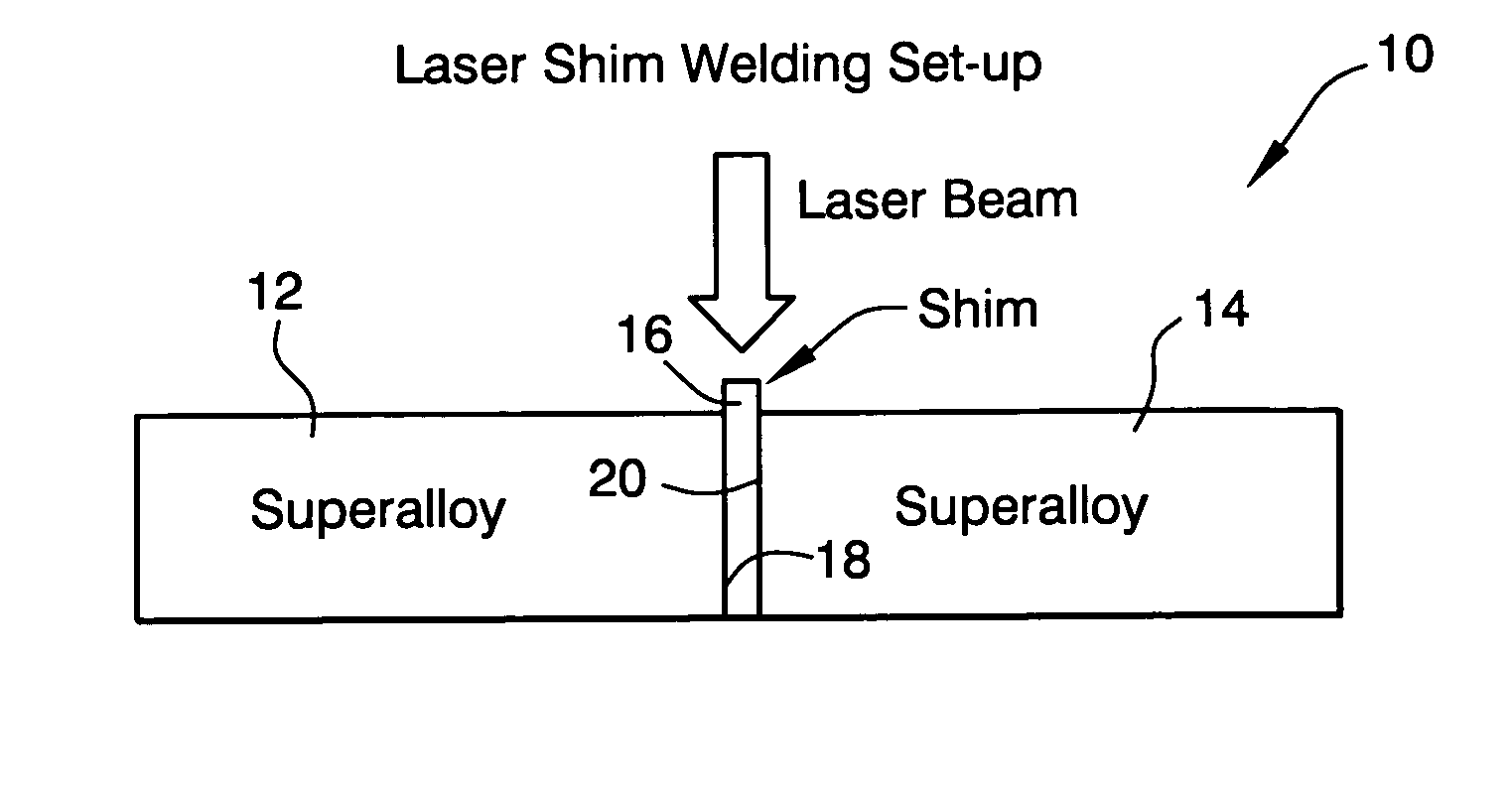
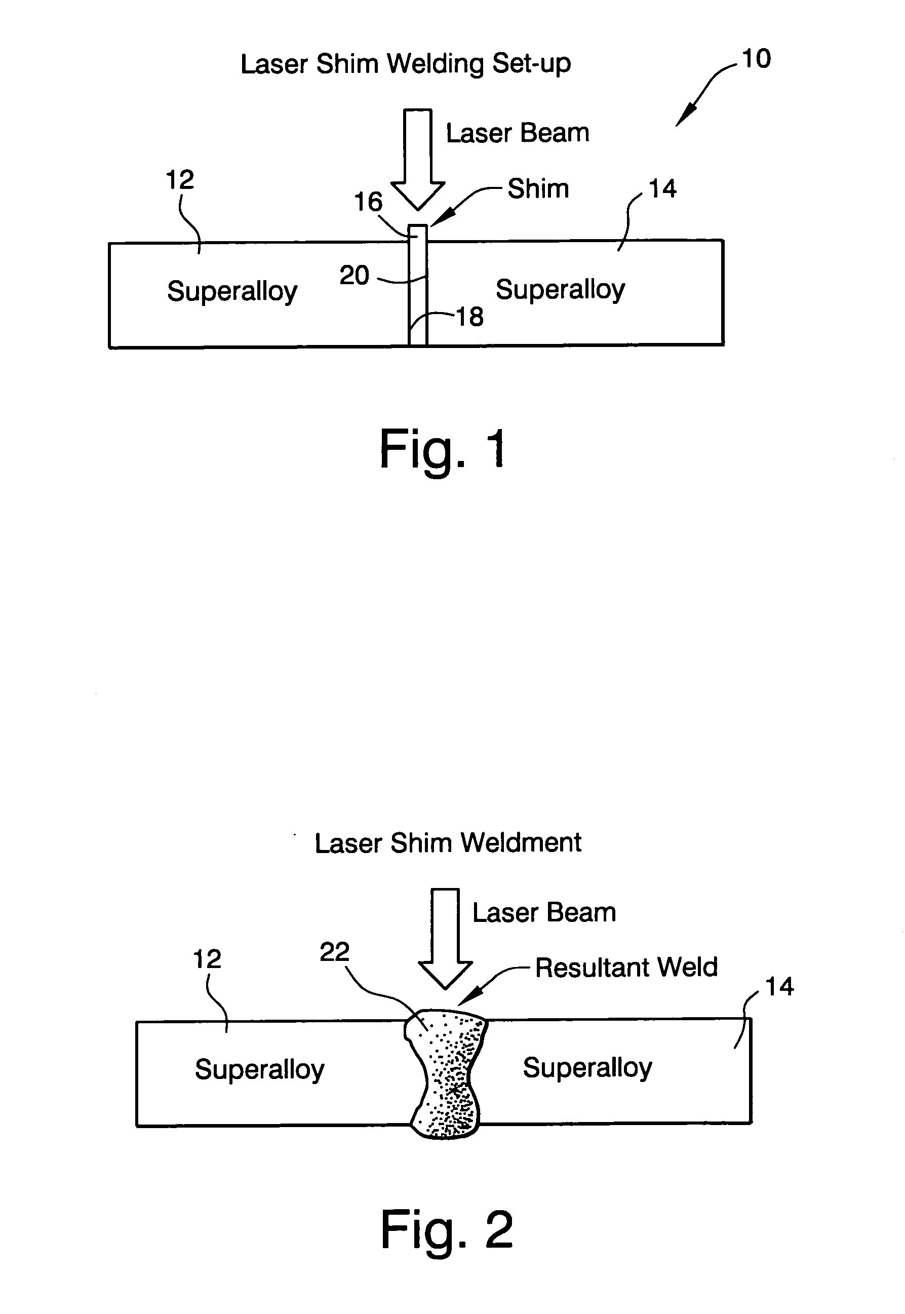
[0017] With reference to FIG. 1, a laser shim welding setup 10 includes a pair of coupons 12, 14 of a nickel-based superalloy (for example, GTD-222), with a shim 16 inserted between opposed faying surfaces 18, 20 located on either side of the nickel-based or cobalt-based shim 16. In the disclosed example, the shim 16 is between 0.010 and 0.040 inch thick, and note that the height of the shim extends about 0.10 to 0.150 inch over that of the joint depth, i.e., over the height or thickness of the coupons 12 and 14. The weld joint mock-ups are fit-up with weld joint gaps from 0 to 0.010 inch (between the shim 16 and faying surfaces 18, 20), and tack welded using a lower power setting with a laser beam. Spot tacks may be made every one half inch along the length of the joint.

[0018] In the disclosed example, the welding parameters used for the laser shim welding process may be as follows: [0019] Wattage: 1000-3500 [0020] Speed: 8 to 30 ipm (inches per minute) [0021] Focal Length: 7½ inc...


PUM

PropertyMeasurementUnit
thicknessaaaaaaaaaa
Thicknessaaaaaaaaaa
thicknessaaaaaaaaaa

Abstract

A method of laser beam welding at least two adjacent superalloy components includes (a) aligning the components along a pair of faying surfaces but without a backing plate; (b) placing a superalloy shim between the faying surfaces; (c) welding the components together using a laser beam causing portions of the superalloy components along the faying surfaces to mix with the superalloy shim; and cooling the components to yield a butt weld between the components.

Description

BACKGROUND OF THE INVENTION [0001] This invention relates to gas turbine technology generally, and specifically, to a laser beam welding process for joining nickel, cobalt and iron-based superalloys. [0002] Nickel-based superalloys like Rene N5, typically contain greater than 10% refractory elements and are generally viewed as unweldable. The use of a low heat input welding process, however, such as laser or electronic beam, has produced crack-free weld joints over a very narrow range of welding conditions. One drawback to these beam processes is the directional grain growth in the fusion zone which forms a distinct dendritic boundary in the center of the weld zone. This type of grain structure makes the joint vulnerable to centerline cracking and results in very poor fatigue strength. For example, the fatigue life of an electron beam welded N5 / GTD-222 joint at 1200° F. and 0.9% strain fails at about 100 cycles, which is five times lower than that of lower strength GTD-222 base meta...

Claims


Application Information

Patent Timeline
Patent Type & Authority Applications(United States)
IPC IPC(8): B23K26/20
CPCB23K26/06B23K26/203B23K26/26B23K26/3206F05D2250/52F01D5/14F01D25/00F05D2220/31F05D2230/234B23K2201/001B23K26/211B23K26/32B23K2101/001B23K2103/50
Inventor NOWAK, DANIEL ANTHONYFENG, GANJIANGSPIEGEL, LYLE B.
Owner GENERAL ELECTRIC CO
Why Eureka
Try Eureka