Brake control apparatus

a technology of brake control and apparatus, which is applied in the direction of brake systems, brake components, transportation and packaging, etc., can solve the problems of affecting the compactness of the bbw system and and achieve the effect of enhancing the flexibility of the engine room layou

Active Publication Date: 2007-01-25
HITACHI ASTEMO LTD
View PDF9 Cites 47 Cited by
  • Summary
  • Abstract
  • Description
  • Claims
  • Application Information

AI Technical Summary

Benefits of technology

[0004] Accordingly, it is an object of the present invention to provide a brake control apparatus which is effective for enhancing flexibility of engine room layout.

Problems solved by technology

This adversely affects compactness of the BBW system and flexibility of engine room layout.

Method used


Image

  • Brake control apparatus
  • Brake control apparatus
  • Brake control apparatus

Examples


first embodiment

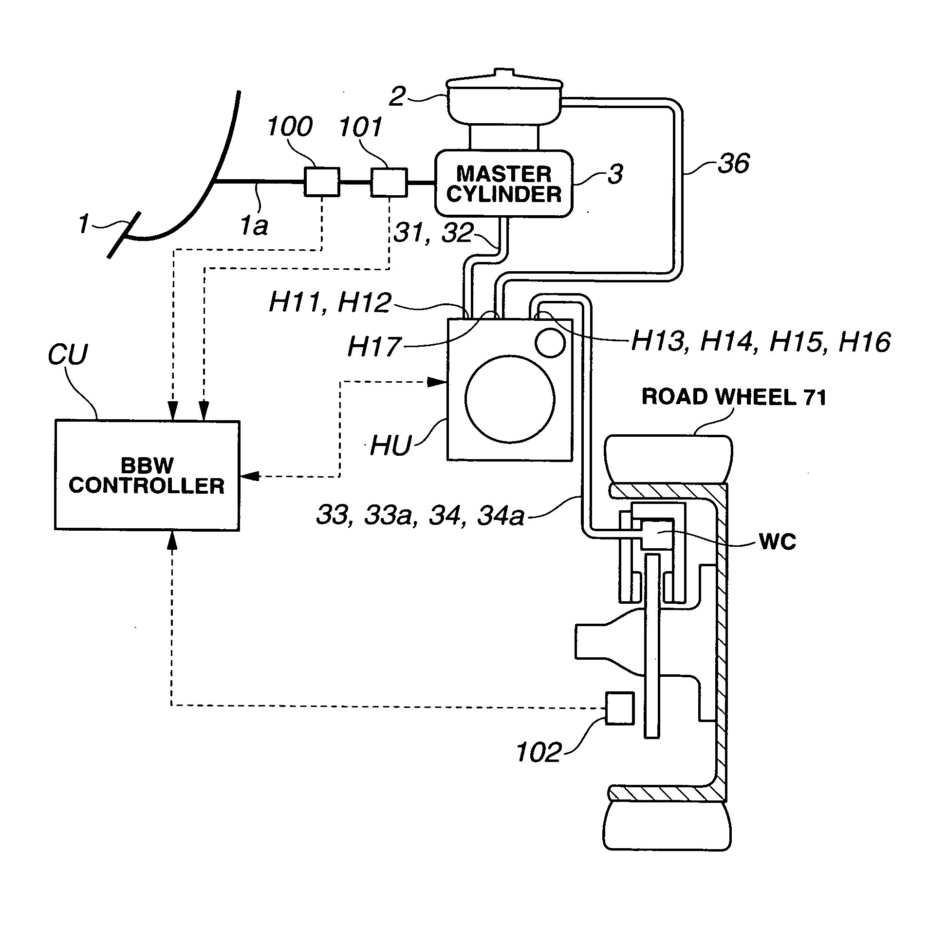
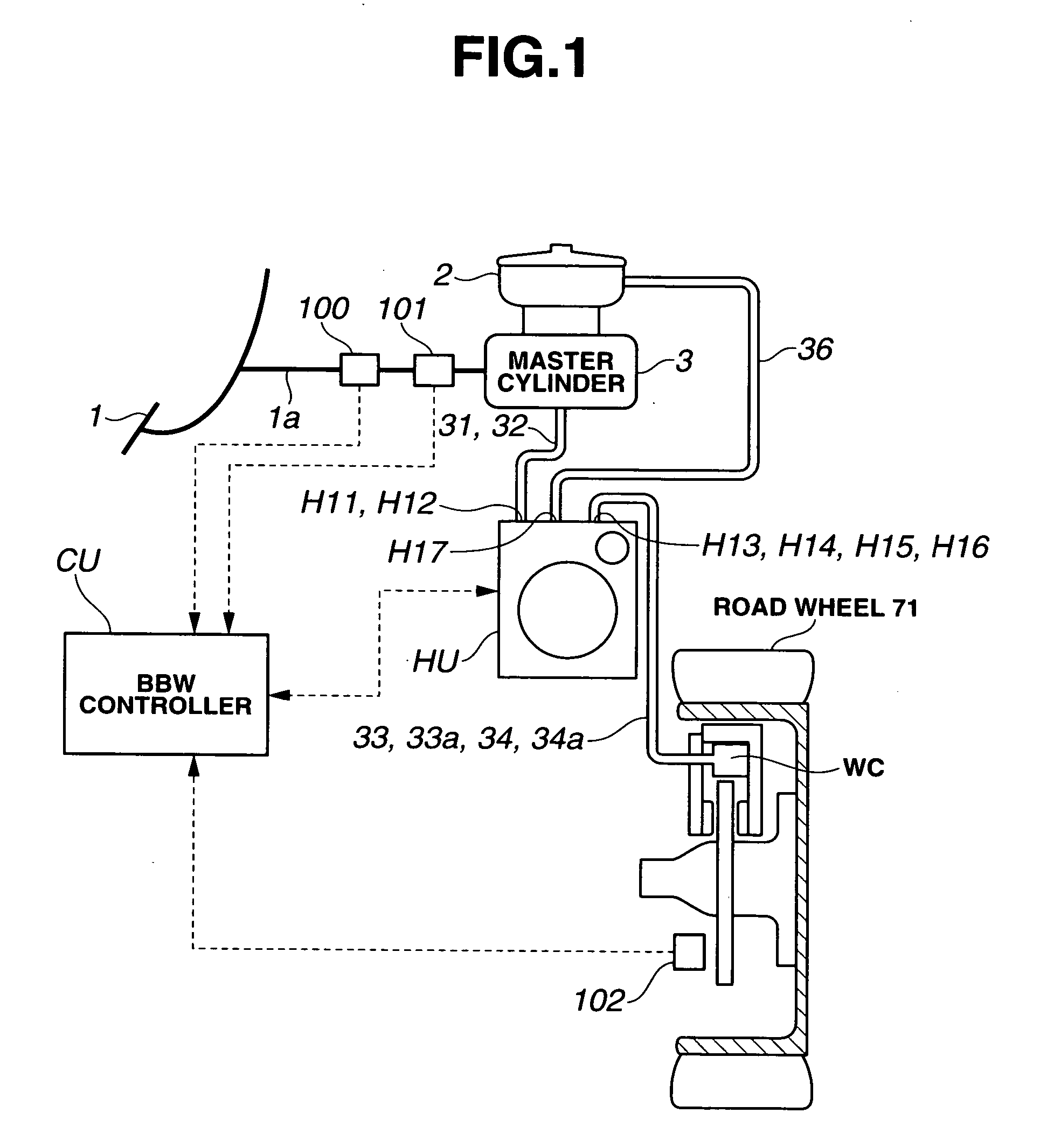
[0028] As shown in FIG. 3, stroke simulator SS is mounted within hydraulic brake unit HU, not located near master cylinder 3. On the other hand, since the brake control apparatus of the first embodiment includes no accumulator, stroke simulator SS is installed in the space for accumulator. As a result, a space is produced around master cylinder 3. The above construction of hydraulic brake unit HU allows master cylinder 3 to be of a conventional type, serving for cost reduction. Stroke simulator SS is described below in detail.

[0029] A fluid pressure sensor 21 is disposed in fluid passage 31, while a fluid pressure sensor 22a is disposed in fluid passage 32. Further, fluid pressure sensors 23, 23a, 24 and 24a are disposed in fluid passages 33, 33a, 34 and 34a, respectively.

[0030] Gear pump 10 is disposed between a pump inlet fluid passage 35 and a pump outlet fluid passage 370. Pump inlet fluid passage 35 is hydraulically connected to fluid reservoir tank 2 via fluid passage 36, whi...

second embodiment

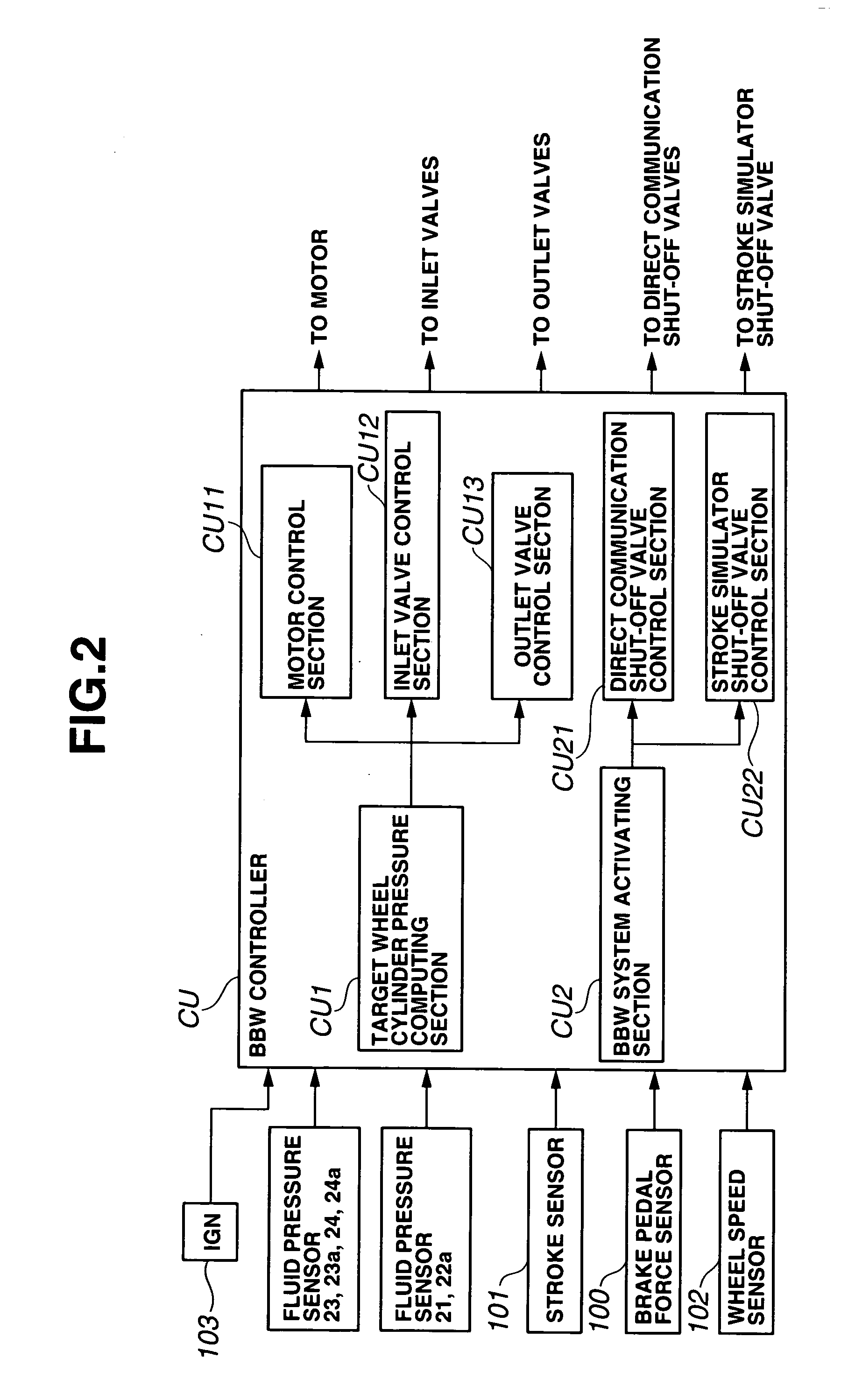
[0056] In the second embodiment, stroke simulator shut-off valve control section CU22 computes a desired characteristic of pedal depressing force in accordance with the sensor signals, computes the opening degree of stroke simulator shut-off valve S1 in accordance with the desired characteristic, and issues and outputs a corresponding command signal. As shown in FIG. 9, stroke simulator SS is formed having a minimum volumetric capacity to store a necessary amount of brake fluid. This arrangement is effective for enhancing compactness of stroke simulator SS.

[0057] The pedal depressing force characteristic may be changed in accordance with a driving state of the vehicle. If a stroke simulator is disposed close to a master cylinder outside a hydraulic brake unit, cooperative control of a BBW system is implemented by providing communication lines between the stroke simulator and the hydraulic brake unit or providing an additional controller for the stroke simulator which is disposed on ...


PUM


Abstract

A brake control apparatus includes a brake unit. The brake unit includes: a first port set hydraulically connected to a master cylinder via a first fluid line set; a second port set hydraulically connected to a wheel cylinder set via a second fluid line set; a first fluid passage hydraulically connecting the first port set to the second port set; a first switching valve arranged to vary a state of fluid communication through the first fluid passage; a fluid pressure source arranged to produce a fluid pressure supplied to the second port set; a fluid accommodating section adapted to accommodate a variable amount of brake fluid; a branch fluid passage hydraulically connecting the first port set to the fluid accommodating section; and a second switching valve arranged to vary a state of fluid communication through the branch fluid passage.

Description

BACKGROUND OF THE INVENTION [0001] The present invention relates generally to vehicle brake control, and more particularly to vehicle brake-by-wire control. [0002] Japanese Patent Application Publication No. 2000-168536 shows a brake-by-wire system, henceforth referred to as “BBW system”, which includes an accumulator for storing pressurized brake fluid and operates hydraulic brakes by supplying the pressurized brake fluid to wheel cylinders. Under normal operating conditions, the brake fluid pressure of the accumulator is kept as high as possible in order to quickly supply a hydraulic pressure needed to generate a desired braking force. This BBW system includes a stroke simulator for allowing a desired brake pedal stroke and further providing a simulated feel of brake pedal depression to the driver. SUMMARY OF THE INVENTION [0003] The BBW system of Japanese Patent Application Publication No. 200-168536 includes no power boosting device such as a vacuum power booster. This is effect...

Claims


Application Information

Patent Timeline
Patent Type & Authority Applications(United States)
IPC IPC(8): B60T8/36
CPCB60T8/368Y10S303/10B60T8/409B60T8/4081B60T11/16B60T13/161
Inventor NAKAZAWA, CHIHARU
Owner HITACHI ASTEMO LTD
Why Eureka
Try Eureka