Position detecting system, responder and interrogator, wireless communication system, position detecting method, position detecting program, and information recording medium

Inactive Publication Date: 2007-01-25
BROTHER KOGYO KK
View PDF43 Cites 51 Cited by
  • Summary
  • Abstract
  • Description
  • Claims
  • Application Information

AI Technical Summary

Benefits of technology

[0017] With the above problems being taken into consideration, an object of the present invention is to take advantage of the characteristics of the UWB wireless communication described in the above items (1) to (6) to achieve low power consumption and accurate distance measurement, and to provide a position detecting system that includes a responder and an interrogator that can specify the d

Problems solved by technology

In a identification system containing the above-described conventional wireless tags, however, the distance from a wireless tag to an interrogator cannot be measured with adequate precision, though commercial products with the wireless tags can be distingui

Method used


Image

  • Position detecting system, responder and interrogator, wireless communication system, position detecting method, position detecting program, and information recording medium
  • Position detecting system, responder and interrogator, wireless communication system, position detecting method, position detecting program, and information recording medium
  • Position detecting system, responder and interrogator, wireless communication system, position detecting method, position detecting program, and information recording medium

Examples


Example

(1) First Embodiment

[0040] Referring to FIGS. 1 to 8, a first embodiment of the present invention will be described.

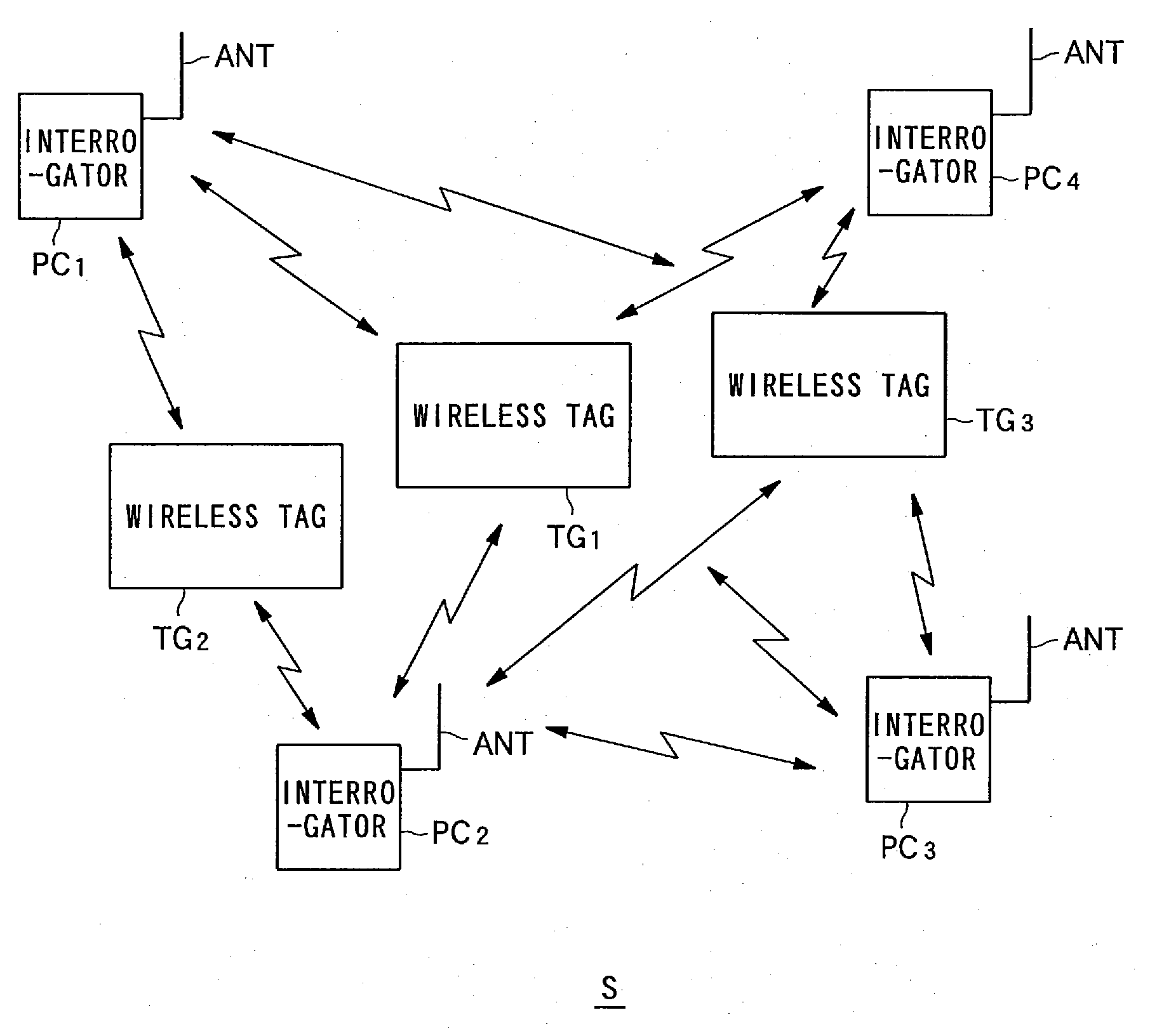
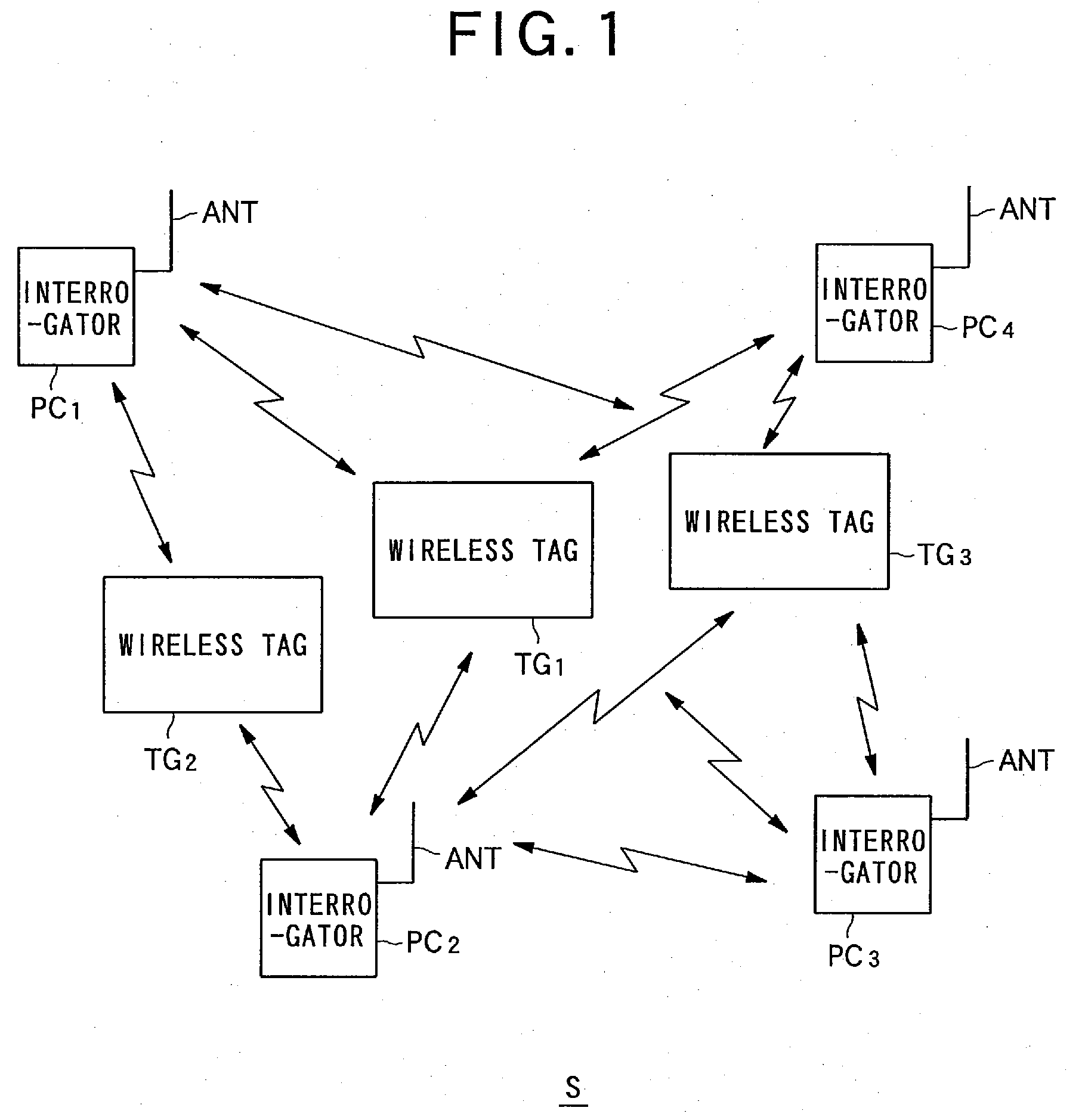
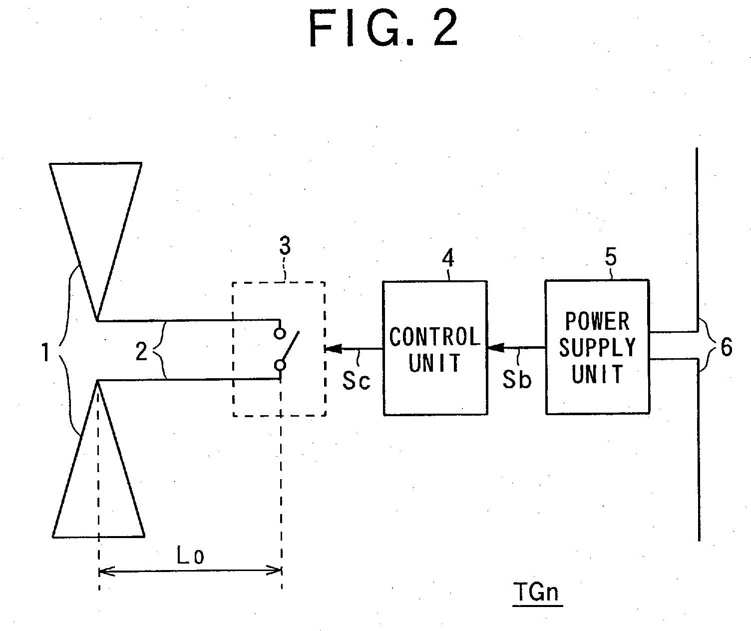
[0041]FIG. 1 is a block diagram schematically showing the structure of a wireless communication system in accordance with the first embodiment. FIG. 2 is a block diagram schematically showing the structure of a wireless tag in accordance with the first embodiment. FIG. 3 is a block diagram schematically showing the structure of an interrogator in accordance with the first embodiment. FIGS. 4A and 4B are waveform charts illustrating the operations of a responder and an interrogator in accordance with the first embodiment. FIGS. 5A to 5D illustrate the operations of the interrogator and the responder in greater detail in accordance with the first embodiment. FIG. 6 is a circuit diagram showing the structure of the wireless tag in detail in accordance with the first embodiment. FIG. 7 shows an exemplary waveform of a pulse signal to be transmitted from the interrogator...

Example

(II) Second Embodiment

[0135] Referring now to FIG. 9 and FIG. 10, a second embodiment of the present invention is described.

[0136]FIG. 9 illustrates the structure of a wireless tag in accordance with the second embodiment. FIGS. 10A and 10B show the correlations with response signals from the wireless tag. In FIG. 9, the same components as those of the wireless tag of the first embodiment shown in FIG. 2 are denoted by the same reference numerals as those in FIG. 2, and explanation of them is not described herein.

[0137] In the above described first embodiment, the wireless tags have transmission paths of constant lengths. However, so-called diode switches may be connected in parallel to the wideband antenna, so that the length of the transmission path of each one wireless tag can be controlled.

[0138] More specifically, as shown in FIG. 9, each wireless tag TGGn in accordance with the second embodiment includes a detection circuit 35, a control unit 34 as a length control unit, ...

Example

(IV) Third Embodiment

[0181] Referring now to FIGS. 16 through 20C, a third embodiment of the present invention is described.

[0182] First, the entire structure and the operation of a wireless communication system in accordance with the third embodiment are described, with reference to FIGS. 16 and 17. FIG. 16 is a block diagram schematically showing the structure of the wireless communication system in accordance with the third embodiment. FIG. 17 is a block diagram schematically showing the structure of an interrogator in accordance with the third embodiment.

[0183] In the structure and operation of the wireless communication system in accordance with the third embodiment, the same components and aspects as those of the structure and operation of the wireless communication system of the first or second embodiment are denoted by the same reference numerals as those in the first and second embodiments, and explanation of them is not described herein.

[0184] Referring first to FIG. ...


PUM


Abstract

There is provided a radio communication system capable of distinguishing objects from one another while taking advantage of the low power consumption and distance measurement ability of the radio communication of the UWB method. A radio tag TGn includes: a characteristic impedance unit (3) for generating a response signal by using a pulse signal received from a broad-band antenna (1); a transmission path (2) having a predetermined length, transmitting the pulse signal received by the broad-band antenna (1) from the broad-band antenna (1) to the characteristic impedance unit (3), and transmitting the generated response signal from the characteristic impedance unit (3) to the broad-band antenna (1); and the broad-band antenna (1) for receiving the pulse signal and transmitting the response signal. The aforementioned pulse wave is transmitted to the radio tag TGn by the UWB method. The response signal from the radio tag TGn is received and the radio tag TGn is identified from the reception waveform.

Description

BACKGROUND OF THE INVENTION [0001] 1. Field of the Invention [0002] The present invention relates to a position detecting system, a responder and an interrogator, a wireless communication system, a position detecting method, a position detecting program, and an information recording medium. More particularly, the present invention relates to a position detecting system that includes a responder (a wireless tag) and an interrogator that exchange information with each other through wireless communication to detect the position of each other, a position detecting method to be utilized in the position detecting system, a wireless communication system that includes the position detecting system, a position detecting program for use in the position detecting system, and an information recording medium on which the position detecting program is recorded. [0003] 2. Discussion of the Related Art [0004] In recent years, so-called wireless tags that are formed with IC chips of 1 mm square or s...

Claims


Application Information

Patent Timeline
IPC IPC(8): H04Q5/22G01S13/02G01S13/75G01S13/87H04B1/69
CPCG01S13/0209H04B1/7163G01S13/878G01S13/751
Inventor TAKI, KAZUNARIOHASHI, TSUYOSHINAGAI, TAKUYA
Owner BROTHER KOGYO KK
Why Eureka
Try Eureka