Cleaning unit and image forming apparatus

a cleaning unit and image forming technology, applied in the direction of optics, electrographic processes, instruments, etc., can solve the problems of difficult scraping with the cleaning blade, wear or damage of the front edge, and the discharge product is difficult to remove from the surface of the photoreceptor, so as to maintain the cleaning performance of residual toner particles at a high level

Inactive Publication Date: 2007-01-25
FUJIFILM BUSINESS INNOVATION CORP
View PDF3 Cites 40 Cited by
  • Summary
  • Abstract
  • Description
  • Claims
  • Application Information

AI Technical Summary

Benefits of technology

[0023] In the cleaning unit according to the first aspect of the present invention, residual toner and additive particles (hereinafter referred to as residual toner component) are captured by fibers of the fiber body and held by the fibers. Adhering substance such as discharge product adhering to the photoreceptor surface is scraped from the photoreceptor surface by the residual toner component held by the fibers of the fiber body. The scraped residue in this way adheres to the residual toner component captured by the fibers. Here, the residual toner component captured by the fibers is replaced with residual toner component which is newly carried to the fiber body, existing on the surface of the photoreceptor and returned to the surface of the photoreceptor. The residual toner component returned to the photoreceptor surface is moved to the cleaning blade located in the down stream because the photoreceptor surface moves cyclically and is removed from the photoreceptor surface by the cleaning blade. Although in the cleaning unit of the present invention, the residual toner component is supplied to the cleaning blade also, particles having a small diameter which function as lubricant by passing between the front end of the blade and the surface of the image carrying because the residual toner component is captured by fibers of the fiber body are likely to be short. By making a contact angle with water at the front end of the cleaning blade larger than conventionally, adhesion force between the photoreceptor and the cleaning blade drops so that friction decreases thereby preventing abrasion and chipping from occurring in the cleaning blade. In the meantime, the contact angle with water at the front end of the cleaning blade is considered to be a factor which is related to adhesion force between the photoreceptor and the cleaning blade and actually by increasing the contact angle with water, friction resistance between the photoreceptor and the cleaning blade is reduced. Further, by increasing the 100% modulus, deformation of the blade front end is suppressed so that the change of the contact area with the photoreceptor is reduced thereby suppressing rise of friction resistance. Consequently, generation of abrasion and chipping in the cleaning blade is suppressed from this point of view also.
[0073] The third aspect of the present invention provides the cleaning unit capable of maintaining the cleaning performance of the residual toner particles at a high level in long periods while removing discharge product sufficiently and the image forming apparatus including the cleaning unit.

Problems solved by technology

However, if the photoreceptor whose surface is hard is used, it is difficult to scrape with the cleaning blade.
The discharge product generated during discharge adheres to the surface of the photoreceptor and particularly the discharge product becomes hard to remove from the surface of the photoreceptor.
Because the blade system is a method of scraping the surface of the photoreceptor mechanically by pressing the front edge of the cleaning blade against the surface of the photoreceptor, if cleaning is executed for a long term, the front edge is worn or damaged or the surface of the photoreceptor suffers from flaws.
Particularly, in recent years when toner particles having a small diameter and a shape approximate to a real sphere have been used to meet a demand for high quality picture, the toner particles pass the cleaning blade easily and a pressure of the front edge to the surface of the photoreceptor needs to be increased, thereby accelerating such a problem about the deterioration of the front edge and damage on the surface of the photoreceptor.
Particularly, when a large amount of prints are made and a non-image portion is kept for long hours in a high-speed machine, lubrication is hampered because no toner particle or additive is supplied to the front edge, deterioration of the front edge is accelerated remarkably thereby inducing a drop in cleaning performance.
On the other hand, the brush type has a weaker mechanical scraping performance to the photoreceptor surface than the blade type and consequently, suffers from a small deterioration in cleaning performance with a time passage.
However, the discharge product cannot be attracted by the brush fibers using electric field different from the toner particles and further, because the brush type provides the weaker mechanical scraping performance as described above, the discharge product cannot be removed sufficiently.
However, the residual toner particles and additive particles easy to catch by the fibers have a so small a diameter that the particles having such a small diameter which can substitute for lubricant between the photoreceptor surface and the front edge portion of the cleaning blade are captured by the fibers and consequently, can be short between the photoreceptor surface and front edge portion.
If the particles having the small diameter which can substitute for lubricant are short, abrasion and chipping are likely to occur in the blade, so that a favorable cleaning in long periods by the cleaning blade is disabled.
The techniques disclosed in JP-A Nos. 2002-244522, 1-161279, and 5-107993 have proposed a method of scraping fine residues from the photoreceptor by means of the fiber body and any technique has a such a problem that the scraping performance of the fiber body becomes uneven in the extension direction of the center axis of the photoreceptor.
If the fiber body is pressed against the photoreceptor strongly in order to raise the scraping performance by the fiber body, mechanical stress to the photoreceptor is raised and even the photoreceptor having a hard surface suffers from excessive abrasion and flaws thereby accelerating deterioration of the fiber body.
Particularly, the techniques disclosed in the JP-A Nos. 2002-244522 and 1-161279 are techniques in which the fiber body is disposed in the downstream in the cyclic moving direction of the photoreceptor surface with respect to the cleaning means and include a fear that the scraping performance by the fiber body is insufficient.
Thus, a necessity of pressing the fiber body against the photoreceptor strongly occurs so that the photoreceptor surface is likely to be worn or damaged excessively or the fiber body itself is deteriorated easily.
Even if the fine residues are scraped by pressing the fiber body against the photoreceptor surface strongly, the fibers are likely to be saturated with the scraped substances and it is difficult to maintain an excellent scraping performance in long periods.

Method used


Image

  • Cleaning unit and image forming apparatus
  • Cleaning unit and image forming apparatus
  • Cleaning unit and image forming apparatus

Examples


example 1

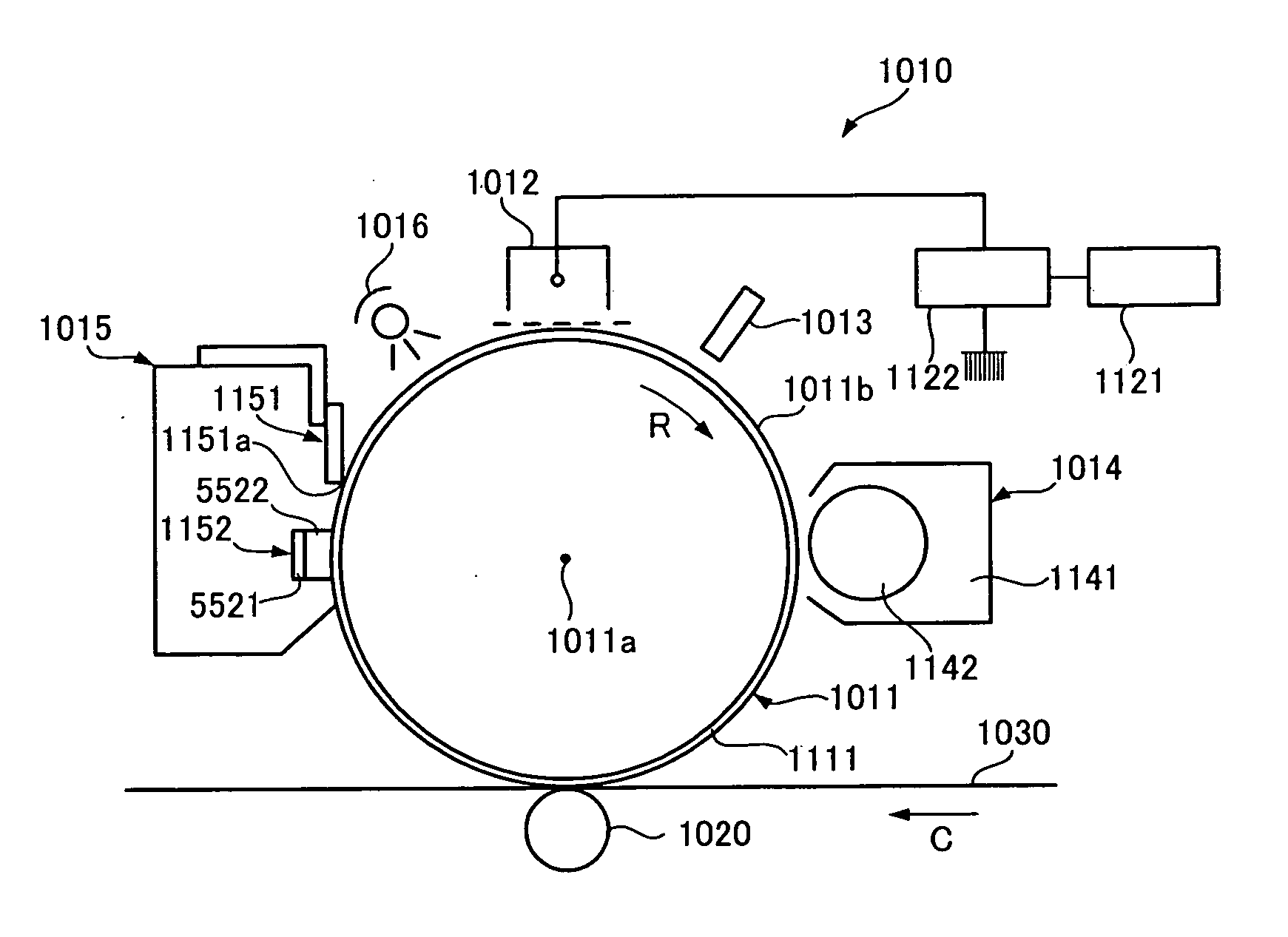
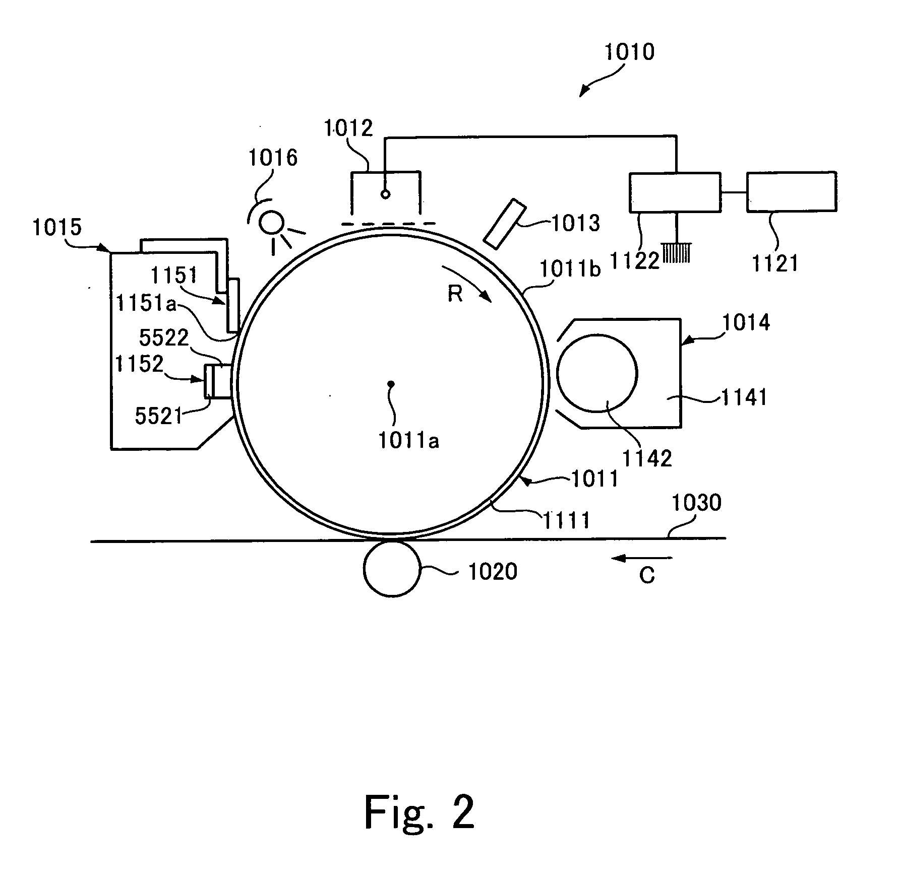
[0230] As a test machine, a reconstructed FUJI XEROX Co., Ltd. Docu-Center Color 500 was used. That is, the photoreceptor A in which the protective layer was formed on the surface thereof was incorporated as the photoreceptor. A cleaning unit equipped with the cleaning blade A and cleaning assistant member A was incorporated. Durability test was carried out about 100,000 pieces under low temperature / low humidity (10° C., 20% RH) and high temperature / high humidity (28° C., 80%) using product developing agent of the Docu-Center Color 500 as developing agent so as to evaluate abrasion of the photoreceptor and flaws on the photoreceptor (photoreceptor roughness). Further, generation of filming was evaluated under low temperature / low humidity and generation of image flow was evaluated under high temperature / high humidity. These results are shown in Table 2 together with comprehensive evaluation.

TABLE 2cleaning unitresult evaluationauxiliarycleaningedgeimagetotalmemberbladeperformanceda...

example 2-5

[0249] The same test and evaluation as the example 1 were executed using the same image forming apparatus as the example 1 except the cleaning blade was changed as shown in Table 2. Its result is shown in Table 2.

example 6-8

[0250] The same test and evaluation as the example 1 were executed using the same image forming apparatus as the example 1 or 2 except the cleaning blade was changed as shown in Table 2. Its result is shown in Table 2.


PUM


Abstract

This invention relates to a cleaning unit comprising: a cleaning blade that keeps a front end of rubber material in contact with the surface with a pressure so as to scrape residual toner left on the surface of the photoreceptor and a fiber body having multiple fibers in contact with the surface of the photoreceptor in the upstream in the cyclic moving direction of the surface of the photoreceptor with respect to the cleaning blade, wherein the cleaning blade satisfies conditions A≧−2.5×B+102 and 6.3≦B≦19.6, where A designates a contact angle (°) with pure water under 23° C., 55% RH and B designates 100% modulus (MPa) at 23° C.

Description

BACKGROUND OF THE INVENTION [0001] 1. Field of the Invention [0002] The present invention relates to a cleaning unit for removing residue such as left toner employed by electrophotographic systems including a copier, facsimile, printer and an image forming apparatus equipped with the same cleaning unit. [0003] 2. Description of the Related Art [0004] According to a conventional electrophotographic system, in toner image forming cycle of charging the surface of a photoreceptor which executes cyclic move, for example, rotation in a predetermined direction about a center axis with a charger, forming a latent electrostatic image on the surface of the photoreceptor by irradiating the surface of the photoreceptor after charged with exposure light and then forming a toner image on the surface of the photoreceptor by developing that latent electrostatic image with a developer, the toner image formed on the surface of the photoreceptor is transferred to a predetermined transfer object surfac...

Claims


Application Information

Patent Timeline
Patent Type & Authority Applications(United States)
IPC IPC(8): G03G21/00
CPCG03G21/0017G03G2221/0005
Inventor SHIGEZAKI, SATOSHIOKUYAMA, HIROESAKANOBE, MAKOTOSHINTAKU, KANJISUGIURA, SATOYASOGA, TATSUYAIWASAKI, JINKURODA, YOSHITAKA
Owner FUJIFILM BUSINESS INNOVATION CORP
Why Eureka
Try Eureka