Noise reduction of aircraft flap

a technology for aircraft and flaps, applied in machines/engines, liquid fuel engines, air-flow influencers, etc., can solve the problems of dominant noise source of aircraft and sound to radiate, and achieve the effect of reducing noise radiating and noise reduction

Inactive Publication Date: 2007-01-25
NASA
View PDF6 Cites 24 Cited by
  • Summary
  • Abstract
  • Description
  • Claims
  • Application Information

AI Technical Summary

Benefits of technology

[0005] In accordance with the present invention, an aircraft flap and method are disclosed which reduce noise radiating from the side of a flap when the flap is deployed. The method targets the noise generation regions of the flap side rather than the vortex formation region of the flap. This reduction in noise is achieved by locating at least one slot adjacent the side of the flap, and then forcing air out through the slot(s) with a suitable mechanism when the flap is deployed.

Problems solved by technology

During airport approach, when the engines of an aircraft are near idle condition and when the high-lift systems and landing gears are deployed, airframe noise is the dominant noise source.
The instabilities in this vortex system and in the strong shear layer that originates on the bottom edge of the flap create an unsteady pressure field at the flap side edge causing sound to radiate.

Method used


Image

  • Noise reduction of aircraft flap
  • Noise reduction of aircraft flap
  • Noise reduction of aircraft flap

Examples


first embodiment

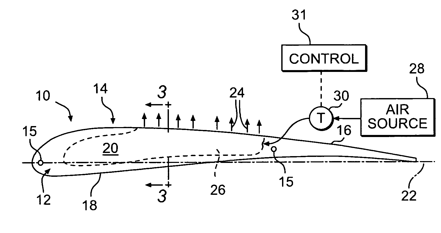
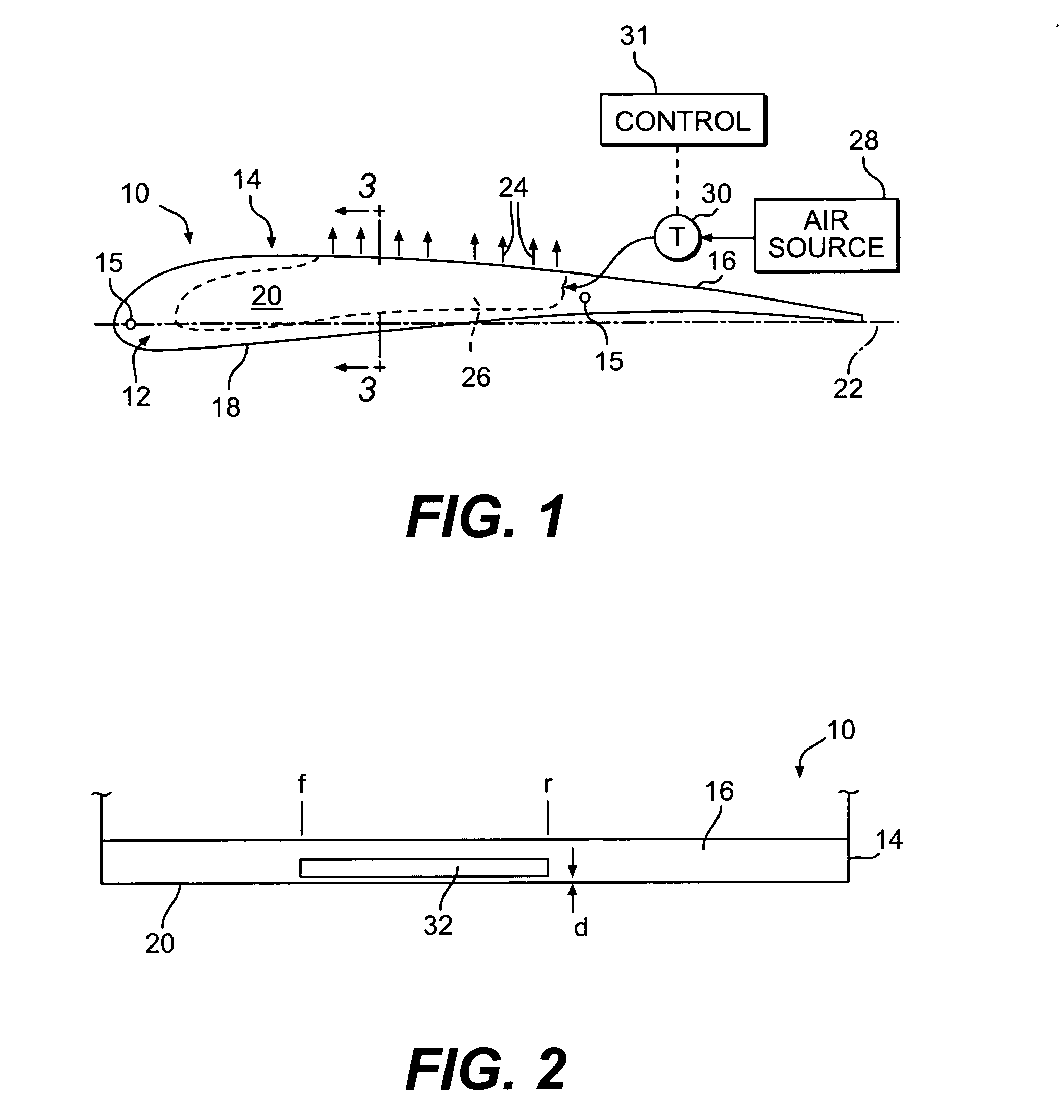
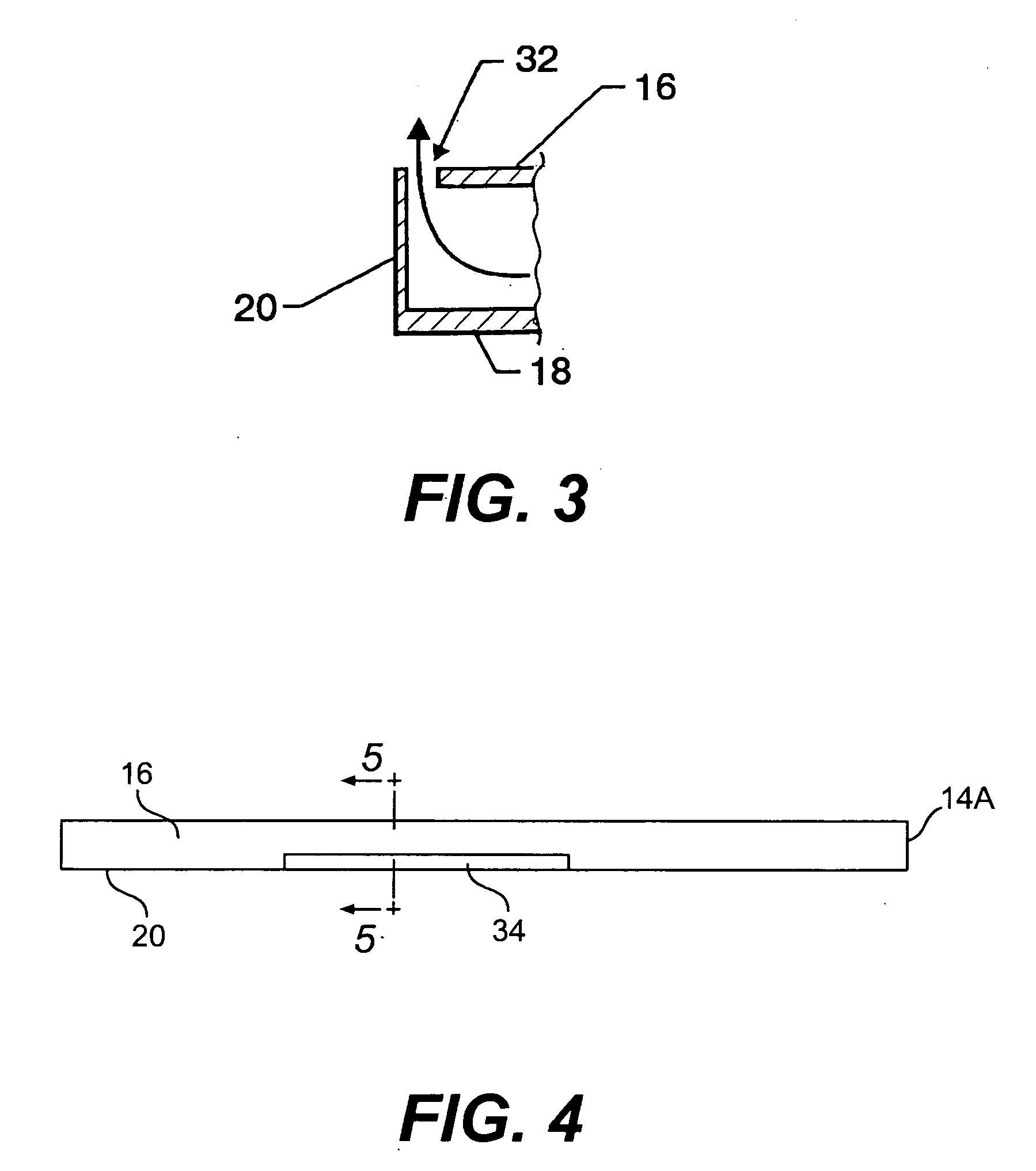
[0026] In accordance with the present invention as shown best in FIGS. 2 and 3, a slot 32 is provided in top surface 16. Slot 32 is rectangular in shape and located a distance d from the side of about 0. The forward edge f of slot 32 is about 0.27 c from the flap leading edge and the rear edge r about 0.60 c from the flap leading edge. The dimensions of slot 32 are about 0.167 c wide by about 0.33 c long, for an open area of about 0. These dimensions are typical of what would be provided for such a flap 10 with tip jet Mach numbers in the range of zero to twice the free stream Mach number (which, as known, during aircraft take off and landing the free stream Mach number is around 0.2). Depicted in FIG. 3 is a cross sectional view through slot 32, showing the flow 24 of air out of slot 32.

[0027] Besides the specific slot 32 depicted, other top surface slots can be provided with different locations, numbers, shapes and sizes as desired or determined to be needed for the particular fla...

third embodiment

[0029] In accordance with the present invention, a slot 36 in a third experimental cap 14B is provided in bottom surface 18 as shown in FIG. 6. Slot 36 has a location which can be the same as slot 32 (as well as other alternate locations as noted); and dimensions which likewise can be the same as slot 32 (and hence slot 36 as depicted on cap 14B appears substantially identical to the depiction of top surface slot 32 of cap 14 in FIG. 2). And in another embodiment (whose depiction would be substantially identical to that of FIG. 4), a slot can be provided at an intersection of bottom surface 18 and side surface 20, with dimensions and locations similar to slot 34 as noted above for the flap 10.

[0030] In accordance with a fourth depicted embodiment, a slot 38 in a fourth experimental cap 14C is provided in side surface 20 as shown in FIG. 7. Slot 38 has a location which can be the same as slot 32 (as well as other alternate locations as noted, or even further forward such as 0.2-0.43 ...


PUM


Abstract

A reduction in noise radiating from a side of a deployed aircraft flap is achieved by locating a slot adjacent the side of the flap, and then forcing air out through the slot with a suitable mechanism. One, two or even three or more slots are possible, where the slot is located at one or more locations selected from a group of locations comprising a top surface of the flap, a bottom surface of the flap, an intersection of the top and side surface of the flap, an intersection of the bottom and side surfaces of the flap, and a side surface of the flap. In at least one embodiment the slot is substantially rectangular. A device for adjusting a rate of the air forced out through the slot can also be provided.

Description

ORIGIN OF THE INVENTION [0001] The invention described herein was made by employees of the United States Government and may be manufactured and used by or for the Government of the United States of America for governmental purposes without the payment of any royalties thereon or therefor.BACKGROUND OF THE INVENTION [0002] During airport approach, when the engines of an aircraft are near idle condition and when the high-lift systems and landing gears are deployed, airframe noise is the dominant noise source. The noise that is generated at the side edge of the flaps has been identified as an important airframe noise component and is a target for noise control. [0003] A number of numerical and experimental studies have been conducted in order to identify and model the noise generation mechanisms at the flap side edge. Flow field measurements in the flap side edge region of a wing with a half-span flap have revealed the presence of a 2-vortex system: a small vortex near the flap side ed...

Claims


Application Information

Patent Timeline
Patent Type & Authority Applications(United States)
IPC IPC(8): F01D5/18
CPCB64C21/04B64C21/08F05D2260/96Y02T50/166Y02T50/673F01D5/145Y02T50/10Y02T50/60
Inventor HUTCHESON, FLORENCE V.BROOKS, THOMAS F.
Owner NASA
Why Eureka
Try Eureka