Micropump for electronics cooling

Inactive Publication Date: 2007-01-25
PURDUE RES FOUND INC
View PDF8 Cites 33 Cited by
  • Summary
  • Abstract
  • Description
  • Claims
  • Application Information

AI Technical Summary

Benefits of technology

[0006] An illustrative embodiment of the present invention provides a micropump that comprises a plurality of microchannels and a vibrating diaphragm that covers the microchannels. The vibrating diaphragm preferably comprises a piezoelectric actuator to vibrate the diaphragm, although other means for actuating the diaphragm to vibrate such as an electrostatic actuator, electromagnetic actuator, shape memory alloy and others can also be utilized instead of piezoelectric actuation. Electrodes are disposed on the surface of the diaphragm facing the microchannels to provide, when energized, an electrohydrodynamic (EHD) enhancement of fluid flow. Alternately or in addition, the electrodes may be disposed on side and/or bottom surfaces of the microchannels to this same end. The vibration motion on the flui

Problems solved by technology

However, the high pressure drops encountered in microchannels have largely precluded their use in practical applications thus far.
The need

Method used


Image

  • Micropump for electronics cooling
  • Micropump for electronics cooling
  • Micropump for electronics cooling

Examples


Embodiment Construction

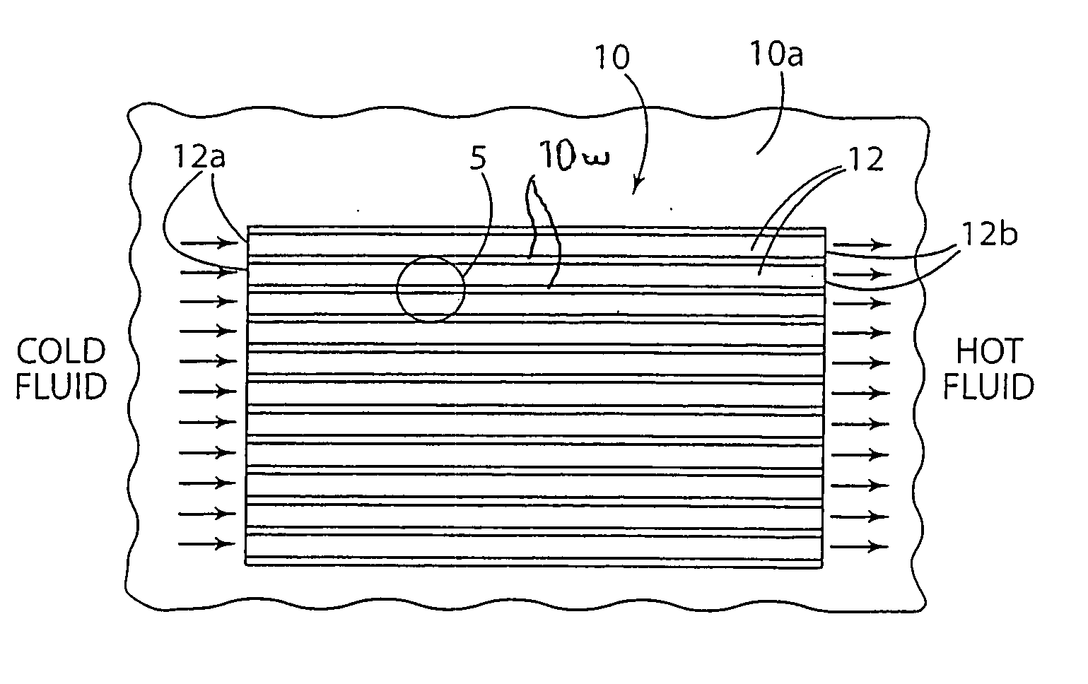
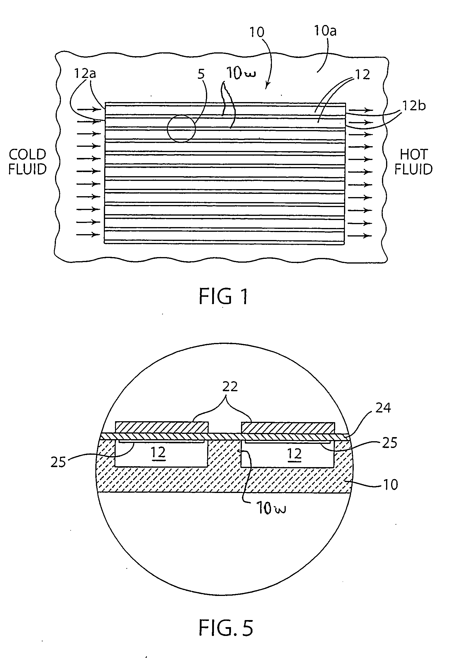
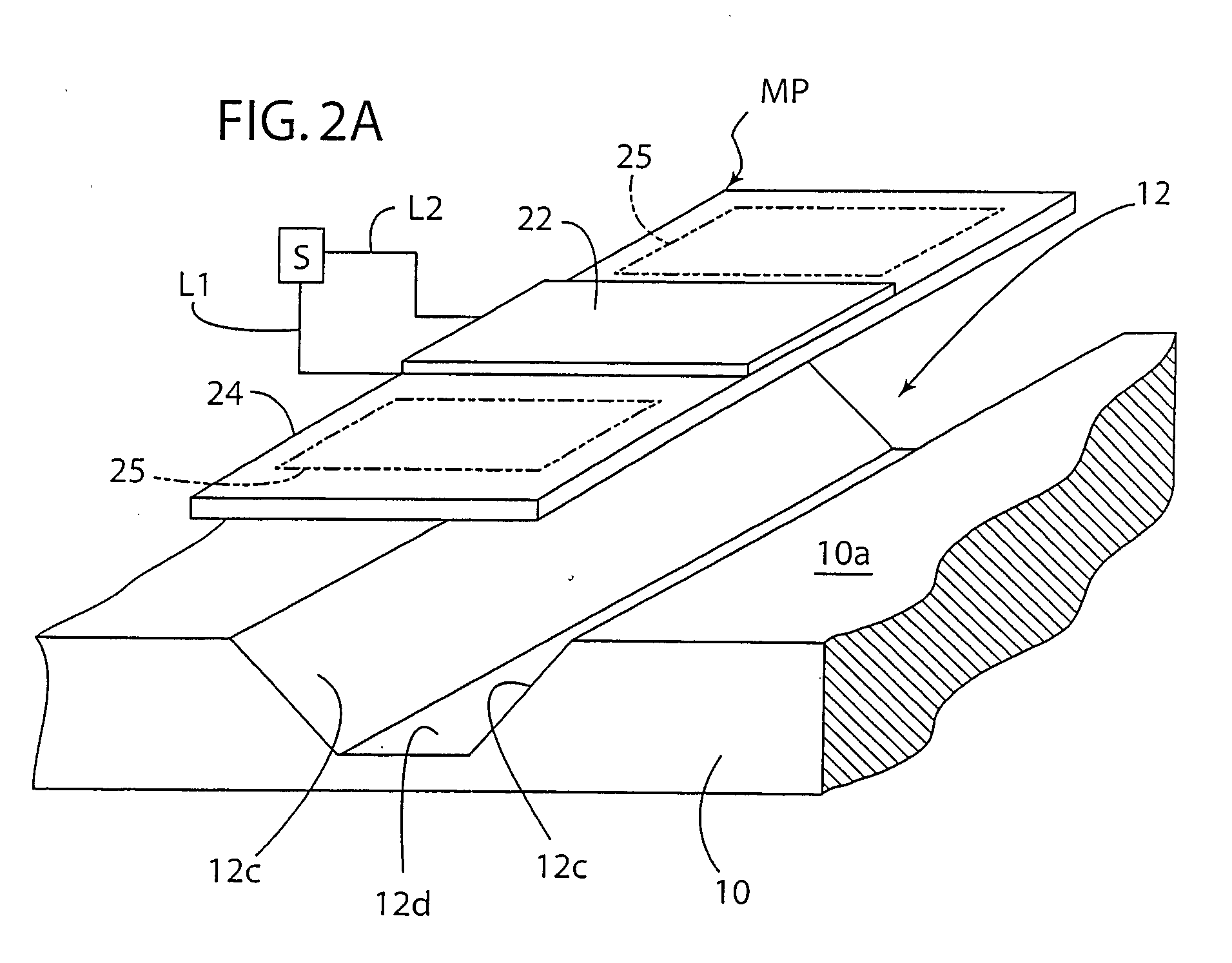
[0022] The present invention provides in an embodiment an electrohydrodynamic (EHD) micropump with fluid flow rate enhancement using a vibrating diaphragm, and useful for, although not limited to, removing heat from a heat-generating electronic component, such as for purposes of illustration and not limitation, a microelectronic IC chip (integrated circuit chip) of an electronic device such as cell phones, laptop computers, personal digital assistance devices, desktop computers, and the like as well as for delivering a drug, medicine or other treatment agent in or as a fluid to a patient. The micropump is advantageous in that it requires less space and electrical power as compared to a conventional micropumps and eliminates the need for an external pump for a microchannel heat sink, in that it provides increased and controllable volume flow rate of the working fluid, and in that it can be incorporated in a microchannel heat sink to provide an improved cooling system for heat-generat...


PUM


Abstract

A micropump including one or more microchannels for receiving a fluid and a plurality of electrodes arranged on a diaphragm and energized in a manner to provide an enhanced electrohydrodynamic flow of fluid through the one or more microchannels. The micropump may be used for pumping a working fluid for removing heat from a heat-generating electronic component or for delivery of a drug, medicine, or other treatment agent as or in a fluid to a patient.

Description

[0001] This application claims benefits and priority of U.S. provisional application Ser. No. 60 / 528,347 filed Dec. 10, 2003.FIELD OF THE INVENTION [0002] The invention relates to an electrohydrodynamic micropump with fluid flow rate enhancement. BACKGROUND OF THE INVENTION [0003] Rapidly decreasing features sizes and increasing power density in microelectronic devices has necessitated development of novel cooling strategies to achieve very high heat removal rates from these devices. For example, heat removal rates in excess of 200 W / cm2 have been projected for the next generation of personal computing devices. Microchannel heat sinks have the potential to achieve these heat removal rates and therefore have been studied for over two decades as described, for example, by Tuckerman and Pease “High performance heat sinking for VLSI”, IEEE Electron Device Letters, Vol. EDL-2, pp. 126-129, 1981, and by Garimella and Sobhan “Transport in microchannels-A critical review”, Annual Review of ...

Claims


Application Information

Patent Timeline
IPC IPC(8): F04B17/00F04B43/04F04B53/10
CPCF04B43/043F04B53/1077F04B43/046
Inventor SINGHAL, VISHALGARIMELLA, SURESH V.
Owner PURDUE RES FOUND INC
Why Eureka
Try Eureka