
Hydrogen iodide manufacturing method and hydrogen iodide manufacturing apparatus

a technology of hydrogen iodide and manufacturing method, which is applied in the direction of hydrogen iodide, chemical/physical/physicochemical process, sulfur compound, etc., can solve the problems of clogging of pipes, unable to directly take out hydrogen iodide anhydride gas, and unable to meet the requirements of hydrogen iodide forming efficiency

Inactive Publication Date: 2007-01-25
KK TOSHIBA
View PDF7 Cites 2 Cited by
  • Summary
  • Abstract
  • Description
  • Claims
  • Application Information

AI Technical Summary

Benefits of technology

[0024] According to yet another aspect of the present invention, there is provided a hydrogen iodide manufacturing apparatus for producing hydrogen iodide and sulfuric acid by causing iodine, sulfur dioxide and water to react with each other, the apparatus comprising: a sulfur dioxide dissolving tank that is a pressure-resistant container for producing aqueous solution of sulfur dioxide by mixing sulfur dioxide and water; a sulfur dioxide source for supplying pressurized sulfur dioxide into the sulfur dioxide dissolving tank; a reaction tank that is a pressure-resistant container for causing the reaction to take place in a pressurized condition; a pipe for supplying the aqueous solution of sulfur dioxide produced in the sulfur dioxide dissolving tank into the reaction tank; iodine-containing aqueous source for supplying iodine-containing aqueous solution into the reaction tank; and at least one back pressure valve for discharging gas therethrough from the sulfur dioxide dissolving tank and the reaction tank, so as to maintain pressure in the sulfur dioxide dissolving tank and the reaction tank above a predetermined level above the atmospheric pressure.

Problems solved by technology

Then, it is not possible to directly take out hydrogen iodide anhydride gas with ease.
One of the factors that lower the hydrogen iodide forming efficiency is clogging of pipes due to deposited sulfur.
However, once the solubility of sulfur dioxide in water is exceeded, sulfur dioxide is no longer dissolved in water and free sulfur dioxide reacts with water and becomes decomposed to produce sulfur, which by turn clogs the pipes of the mixer.
Additionally, since the reaction of forming hydrogen iodide is conducted at or near 100 degrees Celsius, loss of iodide due to sublimation and clogging of pipes are problems that need to be solved in the industry.

Method used


Image

  • Hydrogen iodide manufacturing method and hydrogen iodide manufacturing apparatus
  • Hydrogen iodide manufacturing method and hydrogen iodide manufacturing apparatus
  • Hydrogen iodide manufacturing method and hydrogen iodide manufacturing apparatus

Examples


first embodiment

[0033] [First Embodiment]

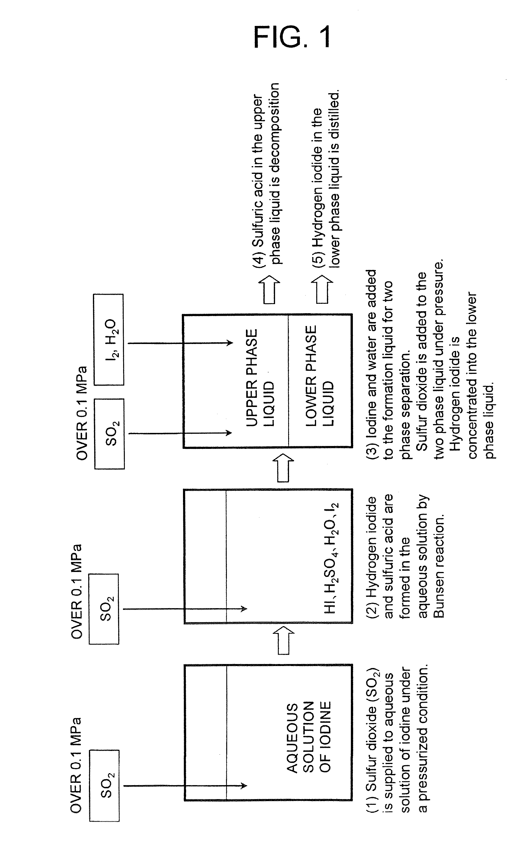
[0034]FIG. 1 is a flowchart of the first embodiment of hydrogen iodide manufacturing method according to the present invention. The flow of the embodiment of hydrogen iodide manufacturing method proceeds in a manner as described below.

[0035] (1) Sulfur dioxide (SO2) is supplied to aqueous solution of iodine under a pressurized condition.

[0036] (2) Iodine, water and sulfur dioxide react with each other under a pressurized condition (Bunsen reaction).

[0037] (3) Iodine and water are added to the formation liquid under a pressurized condition for two-phase separation to produce an upper phase and a lower phase, and the Bunsen reaction is caused to take place by further adding sulfur dioxide to take hydrogen iodide into the lower phase and to concentrate the hydrogen iodide beyond the azeotropic composition.

[0038] (4) After the concentration step of (3) described above, the sulfuric acid in the upper phase liquid is moved to a sulfuric acid decomposition step...

second embodiment

[0045] [Second Embodiment]

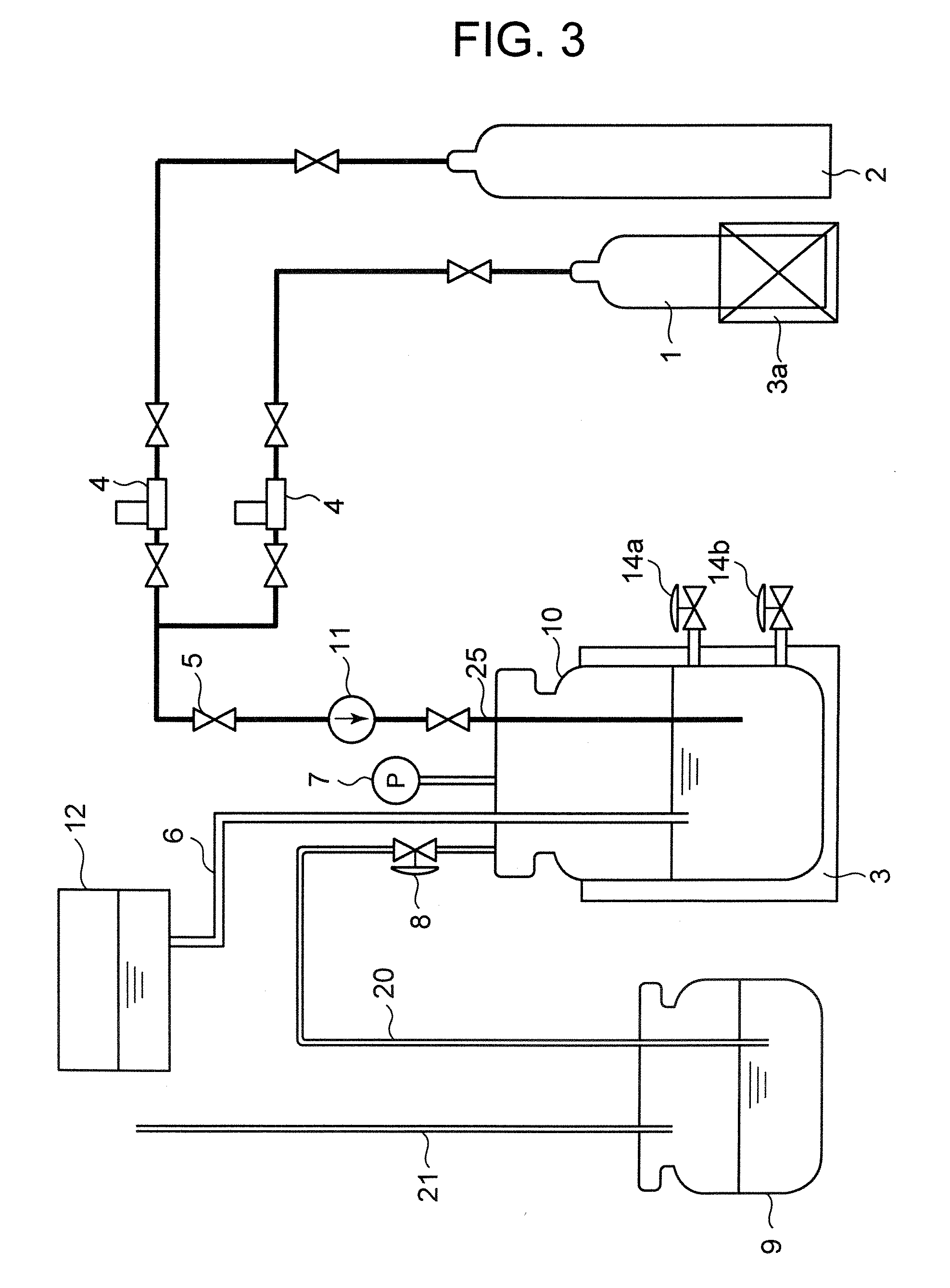
[0046]FIG. 3 is a schematic diagram of a hydrogen iodide manufacturing apparatus that can be used for the second embodiment of hydrogen iodide manufacturing method according to the present invention.

[0047] Referring to FIG. 3, a reaction tank 10 is a pressure-resistant container that is provided with a pressure gauge 7 for detecting the internal gauge pressure of the reaction tank 10. A heater 3 is provided to heat the inside of the reaction tank 10. The reaction tank 10 is equipped with an upper discharge pipe 14a and a lower discharge pipe 14b. A supply tank 12 is arranged above the reaction tank 10 to supply iodine and water into the reaction tank 10 by way of a pipe 6.

[0048] A sulfur dioxide gas cylinder 1 and a nitrogen gas cylinder 2 are arranged at the outside of the reaction tank 10 to respectively feed sulfur dioxide and nitrogen to the reaction tank 10 by way of respective mass flow meters 4, a valve 5, a pressurizing pump 11 and a sulfur dioxid...

third embodiment

[0053] [Third Embodiment]

[0054]FIG. 4 is a schematic diagram of a hydrogen iodide manufacturing apparatus that can be used for the third embodiment of hydrogen iodide manufacturing method according to the present invention. In FIG. 4, the components same as or similar to those of the second embodiment are denoted respectively by the same reference symbols and will not be described repeatedly.

[0055] With this embodiment, a sulfur dioxide dissolving tank 15 is provided in addition to the reaction tank 10. Thus, it is so arranged that aqueous solution of sulfur dioxide that is formed in the sulfur dioxide dissolving tank 15 is transferred to the reaction tank 10 by way of the feed pipe 6 and a feed valve 22.

[0056] The sulfur dioxide dissolving tank 15 is a pressure-resistant container that is provided with a pressure gauge 7 for detecting the internal gauge pressure of the sulfur dioxide dissolving tank 15. A heater 3 is provided to heat the inside of the sulfur dioxide dissolving ta...


PUM


Abstract

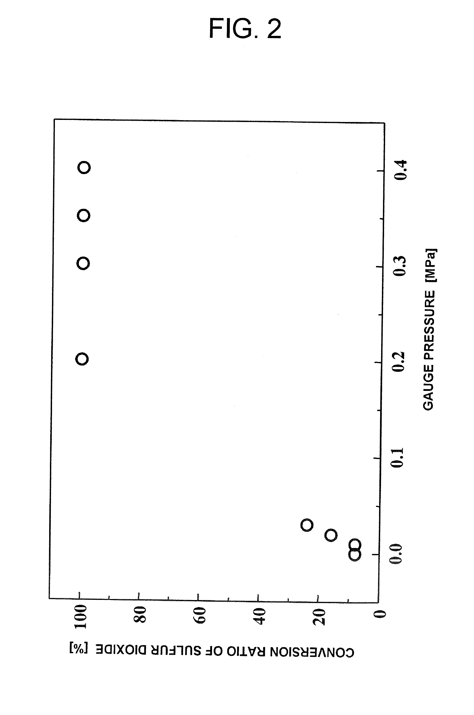
A hydrogen iodide manufacturing method which includes a step of producing aqueous solution of hydrogen iodide and sulfuric acid by causing iodine-containing aqueous solution and sulfur dioxide to react with each other in a pressurized condition. The pressurized condition may be of not lower than 0.1 MPa in gauge pressure. The method may further include: a separation step of adding iodine to the aqueous solution of hydrogen iodide and separating an upper phase containing sulfuric acid relatively to a large extent and a lower phase containing hydrogen iodide relatively to a large extent; and a step of producing hydrogen iodide by adding sulfur dioxide to the upper phase in a pressurized condition and extracting the produced hydrogen iodide to the lower phase.

Description

CROSS REFERENCES TO RELATED APPLICATIONS [0001] The present invention contains subject matter related to Japanese Patent Application No. 2005-213111, filed in the Japanese Patent Office on Jul. 22, 2005, the entire content of which is incorporated herein by reference. BACKGROUND OF THE INVENTION [0002] This invention relates to a hydrogen iodide manufacturing method to be used for manufacturing hydrogen by way of a thermochemical decomposition process (IS method: iodine-sulfur method) and an apparatus to be used for such a method. [0003] In recent years, the use of hydrogen is attracting attention as fuel that can suppress the emission of carbon dioxide (CO2) that is a greenhouse gas. The IS method is known as a technique of manufacturing hydrogen (See, for example, Japanese Patent Publication Nos. 60-52081, 60-48442 and 4-37002, and U.S. Pat. No. 4,127,644). [0004] The principal reactions of the IS method include three reactions expressed by reaction formulas (1) through (3) shown ...

Claims


Application Information

Patent Timeline
IPC IPC(8): C01B7/01
CPCB01J4/001B01J19/24B01J19/245B01J2219/00033Y02E60/364B01J2219/00135B01J2219/00162B01J2219/00186C01B7/135B01J2219/00094Y02E60/36
Inventor TAKAHASHI, RYOUTANAKAMURA, HIDEKIMURAKAMI, KAZUOTAKASE, HARUHIKOJIMBO, NOBORUYAMADA, KAZUYA
Owner KK TOSHIBA
Learn More