
Method of strengthening a microscale chamber formed over a sacrificial layer

a microscale chamber and sacrificial layer technology, applied in the field of chambers in microelectromechanical devices, can solve the problems of device failure, failure at the point(s), and reduce or eliminate the chance of mechanical failure of the chamber, prolong the lifetime and robustness of the devi

Inactive Publication Date: 2007-01-25
EASTMAN KODAK CO
View PDF10 Cites 14 Cited by
  • Summary
  • Abstract
  • Description
  • Claims
  • Application Information

AI Technical Summary

Benefits of technology

[0019] It is an advantage of the present invention to eliminate the stress concentrations in microscale chambers and thereby to decrease or eliminate the chance of mechanical failure of the chamber during fabrication and operation, prolonging lifetime and robustness of the device.

Problems solved by technology

The intrinsic stress of the structural layer forming the chamber may cause it to fail mechanically at the point where the stress is concentrated, resulting in device failure due to the static forces present during device fabrication.
Also, failure may occur during device use due to dynamic or external stresses, again causing failure at the point(s) where stress is most concentrated.
Elimination of these stress concentrations will decrease or eliminate the chance of mechanical failure of the chamber during fabrication, and will also prolong lifetime and robustness of the device.
This device is disadvantaged however, since the polyimide sacrificial layer must be designed with sloped sidewalls to aid in the deposition of the top wall layer.
This is acceptable for many applications, but as miniaturization continues, one would be limited by this design constraint.
Unfortunately, this precision results in increased stress concentrations where corners are covered by a layer of structural layer.

Method used


Image

  • Method of strengthening a microscale chamber formed over a sacrificial layer
  • Method of strengthening a microscale chamber formed over a sacrificial layer
  • Method of strengthening a microscale chamber formed over a sacrificial layer

Examples


third embodiment

[0076]FIG. 6 shows a top view of the improved device chamber with a square top wall 222 having an access port 230 therein, a perimetric wall 224, a perimetric ridge 226 projecting from the perimetric wall 224 into the device chamber 225 and residing adjacent to the top wall 222. However, it should be appreciated that any shape with a sharp corner would not yield all the benefits of the perimetric ridge 226, as the local radius of curvature at each of the sharp corners would be zero.

fourth embodiment

[0077]FIG. 7 shows a top plan view of the improved device chamber. The geometry of the device chamber in this case is rectangular and similar to that shown in FIG. 6 with the exception that the corners rounded with a constant radius of curvature. This increases the minimum local radius of curvature along the surface of the device chamber 325 when compared to the local zero radius of curvature at the corners of the simple rectangular case shown in FIG. 6. Again, there is a top wall 322 having an access port 330 therein, a perimetric wall 324, a perimetric ridge 326 projecting from the perimetric wall 324 into the device chamber 325 and residing adjacent to the top wall 322.


PUM


Abstract

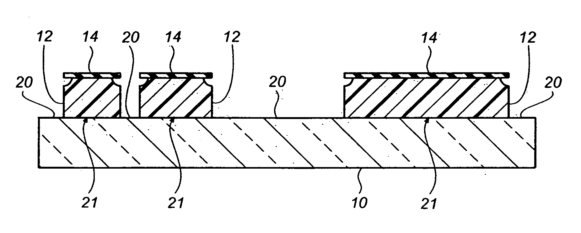
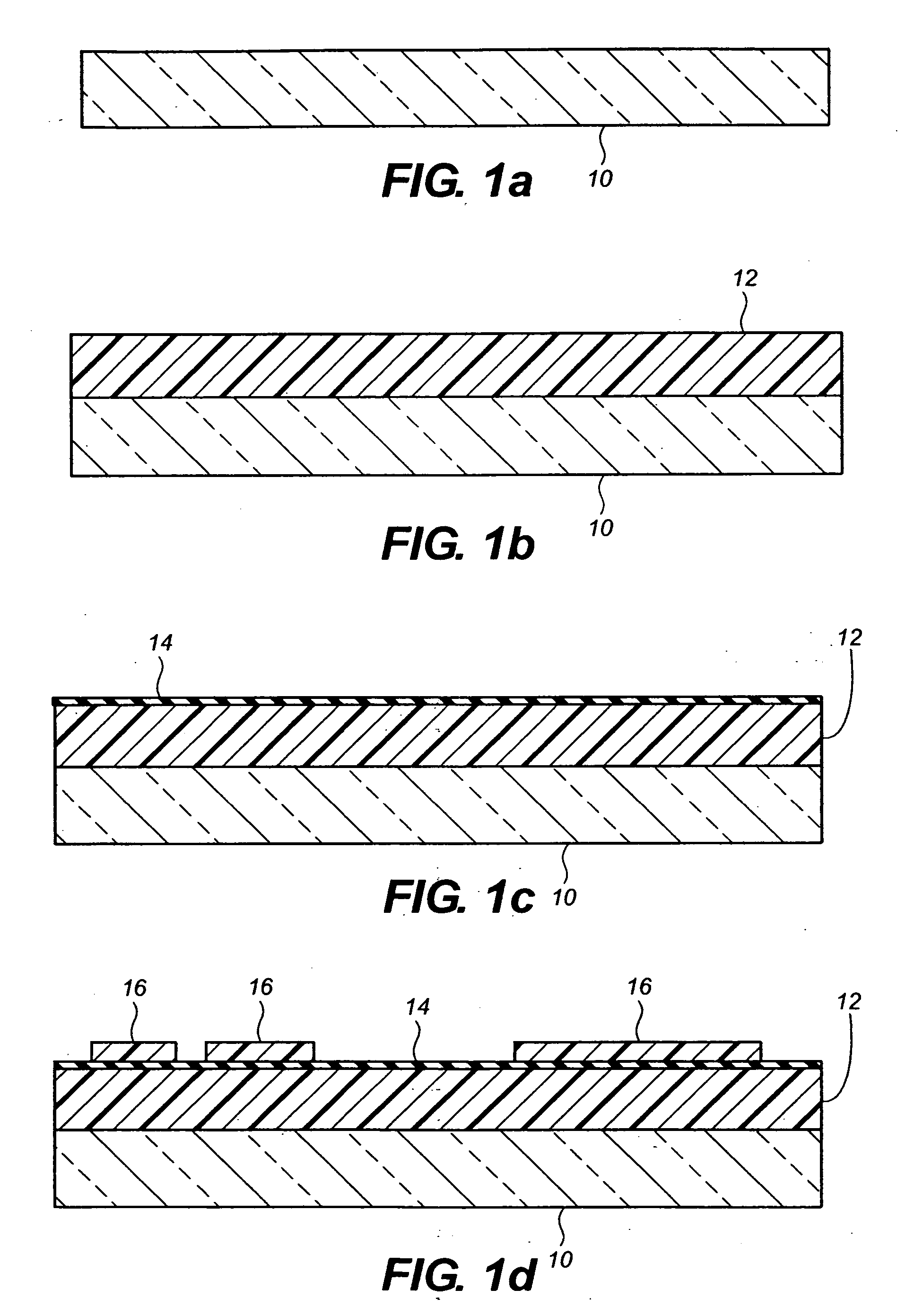
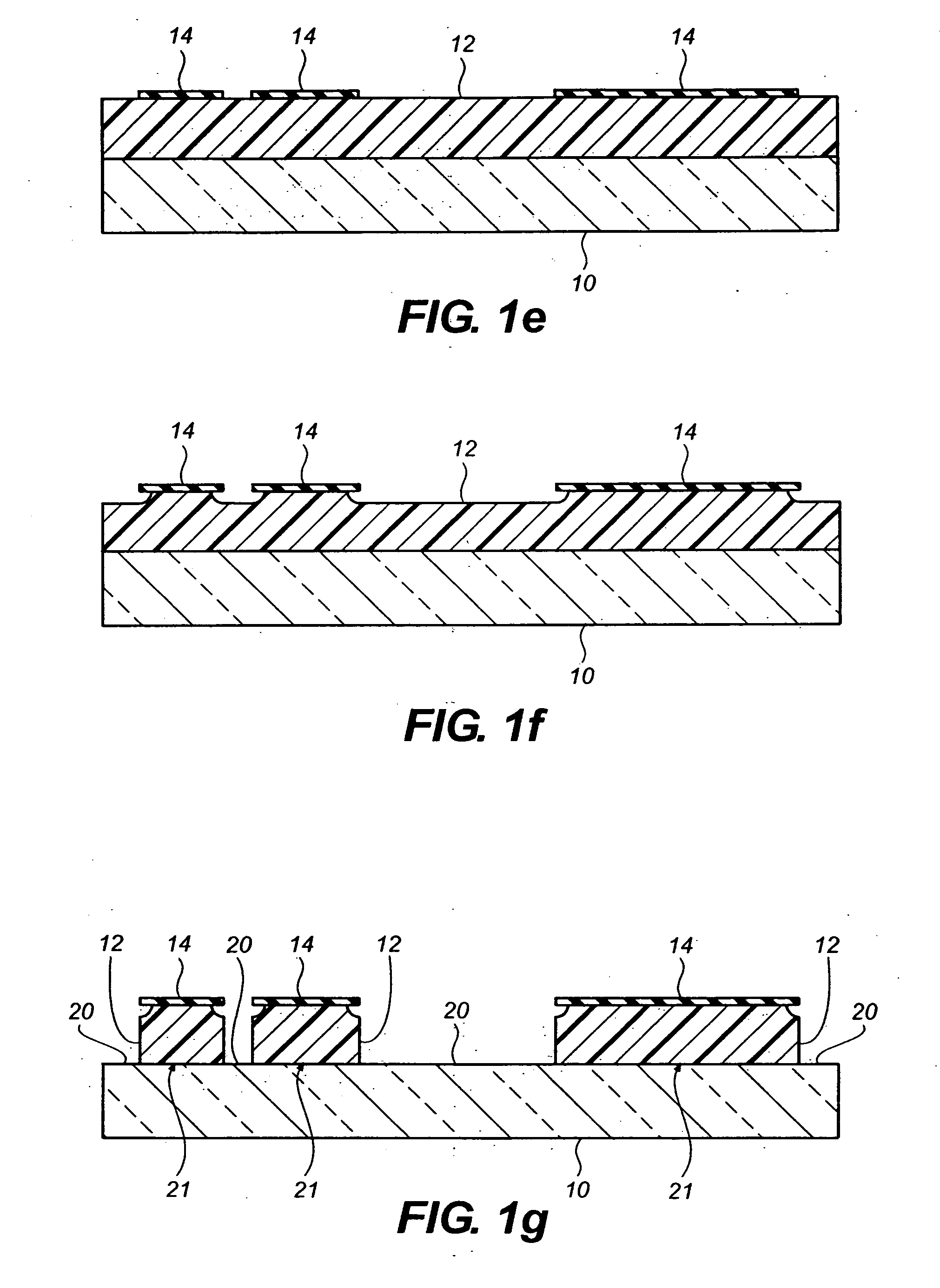
A method for forming an improved chamber for a micro-electromechanical device includes depositing a sacrificial layer on a substrate; depositing a masking layer on a surface of the sacrificial layer; removing at least one predetermined portion of the masking layer down to the sacrificial layer to form an etch pattern; isotropically etching the etch pattern into the sacrificial layer to a partial depth thereof and partially undercutting a remaining portion of the mask material; anisotropically etching the etch pattern into the sacrificial layer to the substrate to form a recessed pattern in the sacrificial layer with at least one anchor region on the substrate surrounding at least one plateau of sacrificial layer; removing the remaining masking layer; depositing a structural layer over the at least one plateau and filling the recessed pattern; providing an access port to the sacrificial layer; and removing the remaining sacrificial layer.

Description

FIELD OF THE INVENTION [0001] The present invention relates to chambers in micro-electromechanical devices. BACKGROUND OF THE INVENTION [0002] In many micro-electromechanical (MEMS) devices, a chamber is an essential component. Often, a structural layer deposited conformally over a patterned sacrificial layer forms this chamber. As will be appreciated by one skilled in the art, the planar nature of the surface micromachining processes traditionally used in MEMS manufacturing causes most standard processes to produce structures that are rectangular or trapezoidal in cross-section. If a chamber is formed over a rectangular or trapezoidal sacrificial mold, there will be a sharp corner, and therefore a stress concentration, in the chamber when the sacrificial layer is removed from beneath the chamber. As is well known to those skilled in the art, local stress is inversely proportional to the local radius of curvature, therefore a sharp corner has a small radius of curvature and a high l...

Claims


Application Information

Patent Timeline
Patent Type & Authority Applications(United States)
IPC IPC(8): H01L21/00H01L21/311B41J2/015B41J2/045
CPCB81C1/00547
Inventor DEBAR, MICHAEL J.
Owner EASTMAN KODAK CO
Learn More