Site specific minimally invasive joint implants

Inactive Publication Date: 2007-01-25
ORTHO VENTIONS
View PDF9 Cites 118 Cited by
  • Summary
  • Abstract
  • Description
  • Claims
  • Application Information

AI Technical Summary

Benefits of technology

[0006] Various embodiments described herein provide an improved method of repairing damaged articular surfaces of the knee and other joints. Further, such embodiments provide an improved implantable device or prosthesis that can replace and augment damaged articular surfaces and articular cartilage. Additionally, various embodiments provide an improved surgical kit to facilitate rapid and successful implantation of prosthetic articul

Problems solved by technology

Like all articulating joints, knee joints are subject to degradation and damage due to, for example, disease, acute injury, and chronic wear.
In particular, the articular cartilage that is found at the articulating surfaces of the knee joint can be

Method used


Image

  • Site specific minimally invasive joint implants
  • Site specific minimally invasive joint implants
  • Site specific minimally invasive joint implants

Examples


Embodiment Construction

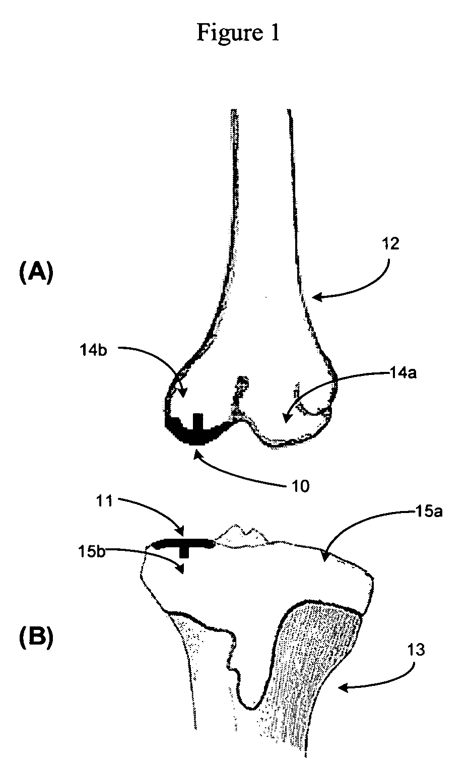
[0017] The following description is intended to convey a thorough understanding of the various embodiments of the invention by providing a number of specific embodiments and details involving devices and methods of augmenting and repairing damaged articular surfaces and cartilage in a knee joint. It is understood, however, that the present invention is not limited to these specific embodiments and details, which are exemplary only. It is further understood that one possessing ordinary skill in the art, in light of known systems and methods, would appreciate the use of the invention for its intended purposes and benefits in any number of alternative embodiments.

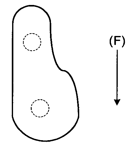
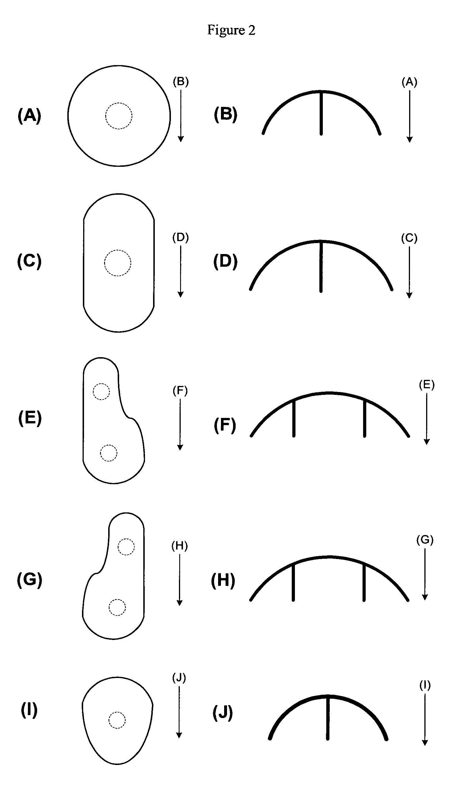
[0018] Throughout this description, the term “cross-sectional geometry,” in reference to the prosthetic articular surface's “cross-sectional geometry,” is intended to mean the two-dimensional geometry, or shape, of the prosthesis when viewed from a plan view. A plan view of the prosthesis is the two-dimensional view of the pr...


PUM

PropertyMeasurementUnit
Sizeaaaaaaaaaa
Volumeaaaaaaaaaa
Radiusaaaaaaaaaa

Abstract

A prosthetic articular surface for implantation in a joint such as the knee is provided. The prosthetic articular surface comprises a contoured plate having two sides, one side of which is a bone-contacting side and the other side of which is an articular side, and at least one post extending from the bone contacting side. A method of placing the prosthesis at an implant site, a guide tool for facilitating implantation, and a surgical kit containing the prosthesis also are provided. The prosthetic articular surface, method of implanting the prosthesis, guide tool for facilitating implantation, and surgical kit containing the prosthesis may be used to replace or augment a damaged joint in the knee.

Description

FIELD OF THE INVENTION [0001] Embodiments of the invention relate to joint implants and methods of placing the joint implants. More particularly, embodiments relate to prosthetic articular surfaces for replacement and augmentation of articulating surfaces of the join, such as the knee, methods of implanting the prostheses, and surgical kits that facilitate successful surgical placement of the prostheses. BACKGROUND [0002] The knee joint is a complex articulating structure linking the tibia and femur of the leg. The knee has been characterized as comprising three separate articulating joints (Henry Gray, F. R. S., Gray's Anatomy, 274 (1974 Running Press)). Two of these joints are condyloid joints located between each condyle (the oval-like head) of the femur and the corresponding tuberosities (the elliptical sockets) of the tibia. The third joint is a semi-arthrodial joint between the patella and the femur. [0003] Like all articulating joints, knee joints are subject to degradation a...

Claims


Application Information

Patent Timeline
IPC IPC(8): A61F2/46A61F2/38A61B17/90A61B17/80
CPCA61B17/1675A61F2310/00359A61B2017/1602A61B2019/303A61F2/28A61F2/30767A61F2/38A61F2/461A61F2002/30616A61F2002/30878A61F2002/4635A61F2002/4662A61F2310/00017A61F2310/00023A61F2310/00029A61F2310/00071A61F2310/00089A61F2310/00095A61F2310/00131A61F2310/00203A61F2310/00239A61F2310/00293A61F2310/00634A61F2310/00766A61B17/1764A61B2090/033
Inventor DUGAS, JEFFREY R.CAIN, EDWARD LYLE JR.
Owner ORTHO VENTIONS
Why Eureka
Try Eureka