
Deposition system

a vacuum deposition and vacuum technology, applied in the direction of vacuum evaporation coating, chemical vapor deposition coating, coating, etc., can solve the problems of inability to obtain constant quality, and inability to stop deposition, so as to prevent deterioration in the quality of film deposition, prevent pollution, and prevent the effect of generating defects

Inactive Publication Date: 2007-02-01
MITSUBISHI ELECTRIC CORP
View PDF10 Cites 0 Cited by
  • Summary
  • Abstract
  • Description
  • Claims
  • Application Information

AI Technical Summary

Benefits of technology

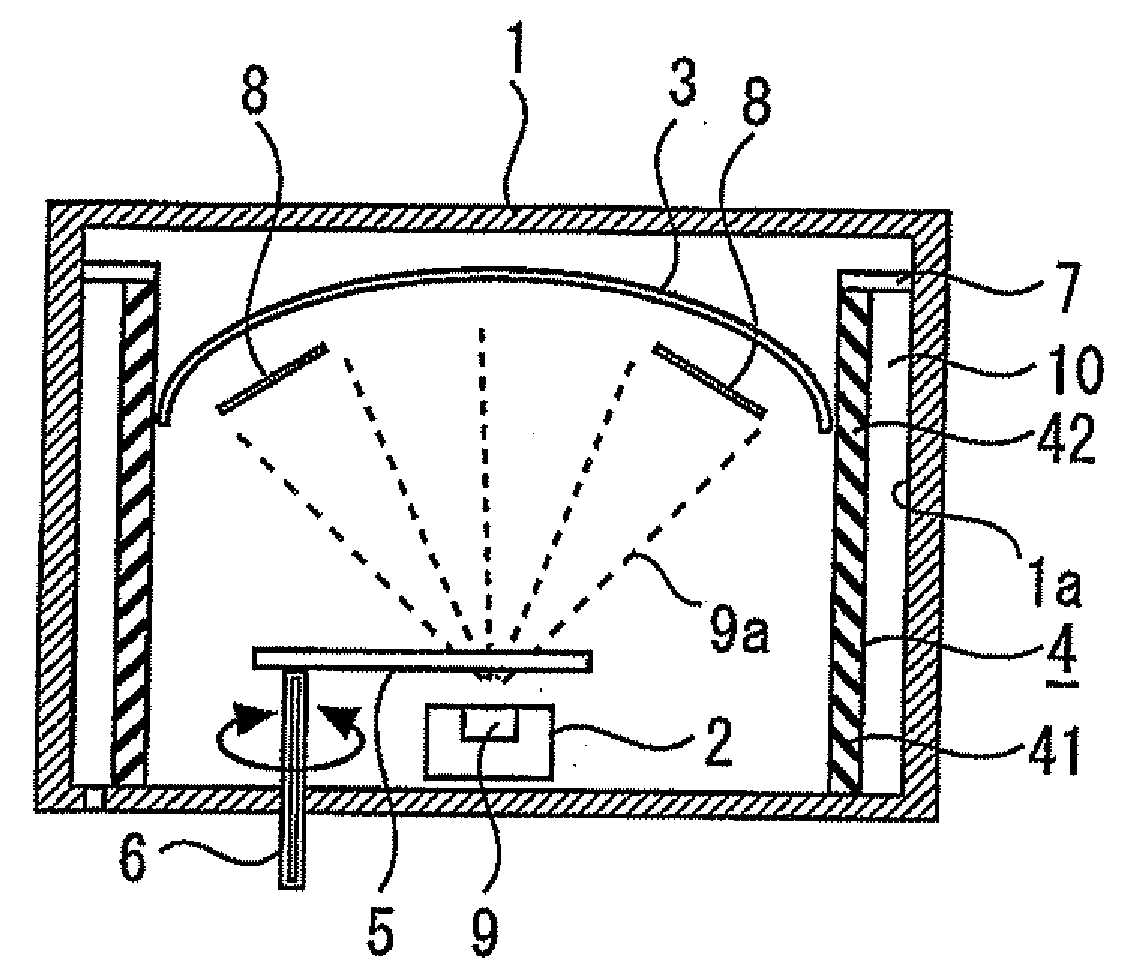
The present invention provides a vacuum deposition system that can prevent deterioration in film quality, pollution in the vacuum vessel, and defects due to adhesion of dust to a subject substrate without decreasing productivity. This is achieved by using an adhesion-prevention member that prevents gas absorbed into the system from reemitting and prevents dust from adhering to the substrate. The adhesion-prevention member is constructed by using a plurality of louver members slanted diagonally down below from the central part side to the inner wall of the vacuum vessel. This prevents the evaporant from the evaporation source from adhering to the inner wall of the vacuum vessel and prevents pollution and defects during film deposition.

Problems solved by technology

In the next deposition, due to radiation heat from the evaporation source or the like, the gas absorbed into this film is emitted to inside the vacuum vessel, It leads to problems that a degree of vacuum in the vacuum vessel is not stable or a composition of residual gas in the vacuum vessel is changed, and thereby characteristics of the thin film to be deposited are changed.
Therefore, a film quality of the thin film to be deposited on the subject substrate immediately after honing of the adhesion-prevention plate is different from a quality thereof after deposition is repeated several times. It leads to a problem that variations are generated among deposition batches, and a constant quality cannot be obtained.
Further, it has been a problem that the film, which adheres to and accumulates on the surface of the adhesion-prevention member, is exfoliated to become dust, which is scattered in the vacuum vessel and the scattered dust adheres to the surface of the subject substrate, leading to a cause of defects.
However, in order to perform such a method, it is inevitable to stop deposition and take the time considerably.
In result, it leads to a problem that productivity is decreased.

Method used


Image

  • Deposition system
  • Deposition system
  • Deposition system

Examples


first embodiment

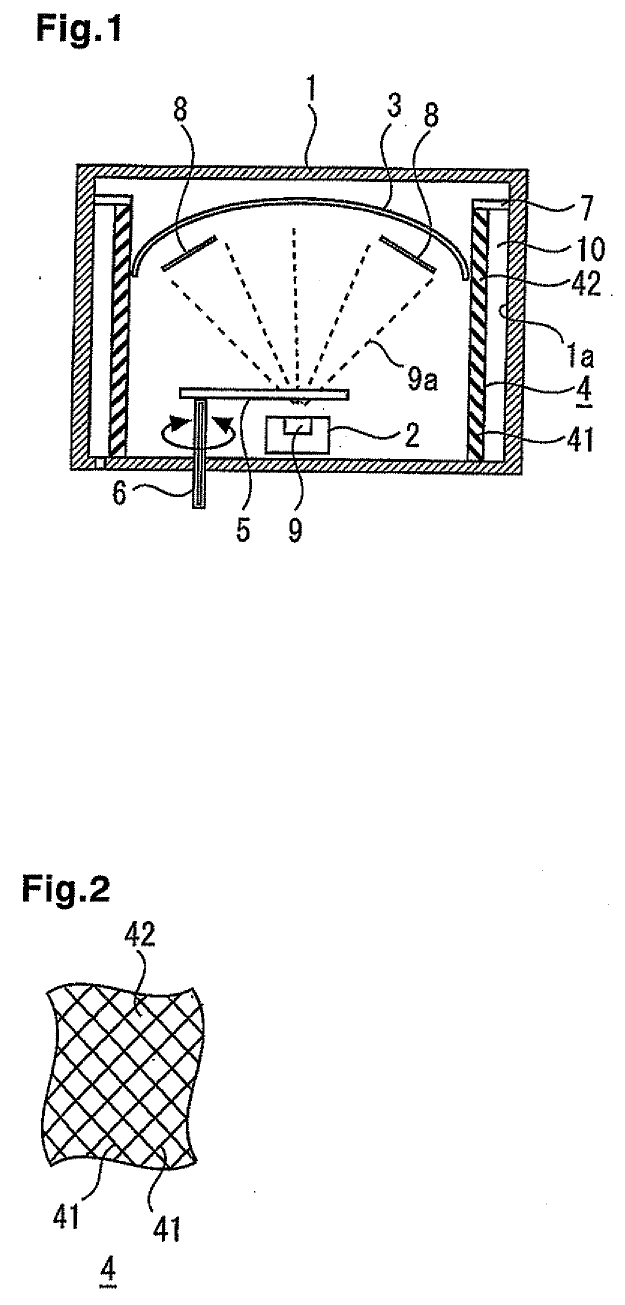
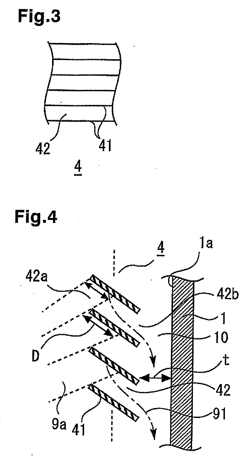
[0018]FIGS. 1 through 4 are views explaining a vacuum deposition system according to a first embodiment of the present invention. FIG. 1 is a vertical cross section showing, by a model, a substantial construction. FIG. 2 is an enlarged elevation view showing, by a model, an example of a case that an adhesion-prevention member is formed of an inclined passage honeycomb body structure. FIG. 3 is an enlarged elevation view showing, by a model, an example of a case that an adhesion-prevention member is formed of a louver-like multiplate structure. FIG. 4 is an enlarged cross section explaining, by a model, an adhesion of an accumulative film to a louver member and exfoliation action thereof. As shown in the figures, this vacuum deposition system comprises a vacuum vessel 1 in the shape of, for example, an approximately quadrangular cylinder, which communicates with or is connected with an unshown exhaust means. An evaporation source holder 2 is provided in a central part at a bottom of ...

second embodiment

[0035]FIG. 5 is a vertical cross section showing, by a model, a construction of a substantial part of a vacuum deposition system according to a second embodiment of the invention. In this second embodiment, a strain provision means 11 is provided for generating strain for the adhesion-prevention member 4. A strain provision means 11 can be a heating means such as a heater for heating the adhesion-prevention member 4 and / or a vibration provision means such as an ultrasonic device for vibrating the adhesion-prevention member 4 (detailed illustrations are omitted for the both). Since other constructions are similar to of the foregoing first embodiment, descriptions thereof will be omitted.

[0036] In the second embodiment as constructed above, after deposition on the subject substrate 8 is completed and before air is introduced, the strain provision means 11 constructed from the heating means such as the heater and / or the vibration provision means such as the ultrasonic device is operat...

third embodiment

[0038]FIGS. 6a and 6b are comparative views for explaining a state of the surface of the louver member used for a vacuum deposition system. FIG. 6a is an enlarged horizontal cross section showing, by a model, a general adhesion-prevention member (adhesion-prevention plate) or the louver member 41. FIG. 6b is an enlarged horizontal cross section showing, by a model, a louver member 41A provided with mirror finish according to the third embodiment of the invention. Except that a whole surface of a component material for the adhesion-prevention member 4 is provided with the mirror finish, constructions of this third embodiment are similar to that of the foregoing first and second embodiments. Therefore, descriptions thereof will be omitted.

[0039] As explained above, in the vacuum deposition system of this third embodiment, the whole surface of the component material for the adhesion-prevention member 4 is provided with the mirror finish. Therefore, anchor effects of the accumulative f...


PUM

PropertyMeasurementUnit
pressureaaaaaaaaaa
adhesionaaaaaaaaaa
structureaaaaaaaaaa

Abstract

A vacuum deposition system comprises a vacuum vessel, an evaporation source holder located in the vacuum vessel for holding an evaporation source and a holding jig provided in the vacuum vessel for holding a substrate facing the evaporation source. An adhesion-prevention member is located at outer peripheries of the evaporation source and the holding jig along an inner wall of the vacuum vessel. The adhesion-prevention member is spaced from the inner wall of the vacuum vessel. The adhesion-prevention member includes members slanted diagonally downward from the central part toward the inner wall. Thereby, the adhesion-prevention member prevents an evaporant from the evaporation source from adhering to the inner wall of the vacuum vessel. A heater on the adhesion-prevention member heats the adhesion-prevention member to exfoliate particles that are deposited to the adhesion-prevention member.

Description

BACKGROUND OF THE INVENTION [0001] 1. Field of the Invention [0002] The present invention relates to a vacuum deposition system preferably used for thin film formation on a surface of a subject material such as a crystal wafer, and relates particularly to improvement of an adhesion-prevention member for preventing evaporants from directly adhering to an inner wall of a vacuum vessel or the like. [0003] 2. Description of the Related Art [0004] In general, a vacuum deposition system for forming a thin film on a surface of a subject material (i.e. subject substrate) such as a crystal wafer has a vacuum vessel and an evaporation source holder provided in the vacuum vessel. The subject substrate is held by an umbrella-like holding jig, which is removably provided above the evaporation source holder in the vacuum vessel, and is vacuum deposited. Conventionally, an adhesion-prevention member constructed from adhesion-prevention plates has been provided along the inner wall of the vacuum ve...

Claims


Application Information

Patent Timeline
Patent Type & Authority Applications(United States)
IPC IPC(8): C23C16/00
CPCC23C14/26C23C14/564C23C14/30
Inventor KOMORI, HIDEKISUMIYOSHI, MASAOTANAKA, TOSHIOKAWASHIMA, MIHARU
Owner MITSUBISHI ELECTRIC CORP
Learn More