Method and apparatus for operating an internal combustion engine

Inactive Publication Date: 2007-02-01
CROWER H BRUCE
View PDF9 Cites 46 Cited by
  • Summary
  • Abstract
  • Description
  • Claims
  • Application Information

AI Technical Summary

Benefits of technology

[0040] It is a further object of this invention to provide an internal combustion engine with a water injection system adaptable to employment on any internal combustion engine to recapture previously wasted heat from the combustion chamber to do work thereby increasing engine efficiency and power.
[0041] It is another object of this invention to provide such a device and

Problems solved by technology

Further, the engine cylinders and pistons and cylinder heads, which are conventionally cooled by water or air, pumped by the engine itself, are cooled during this recapture of heat energy

Method used


Image

  • Method and apparatus for operating an internal combustion engine
  • Method and apparatus for operating an internal combustion engine
  • Method and apparatus for operating an internal combustion engine

Examples


Embodiment Construction

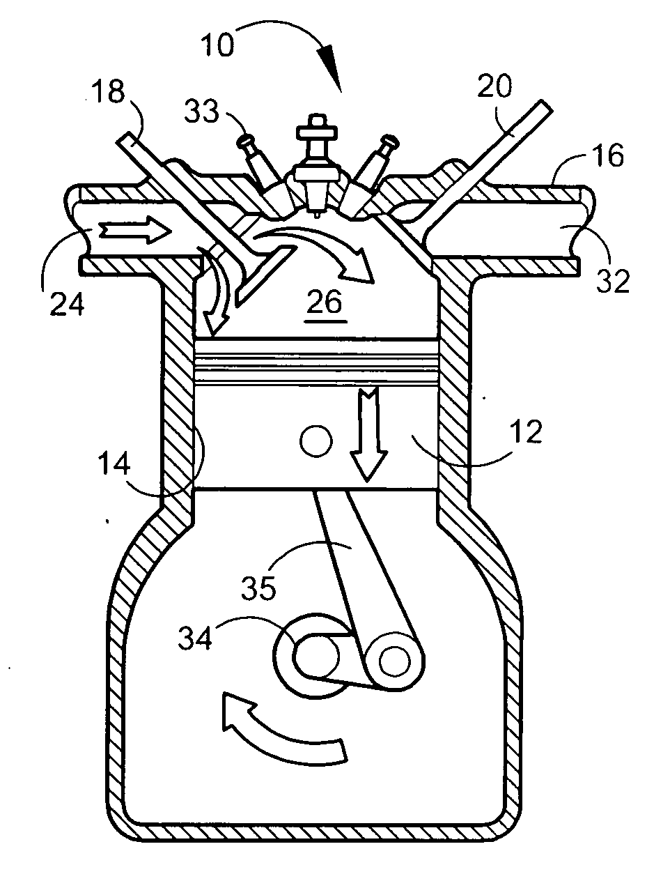
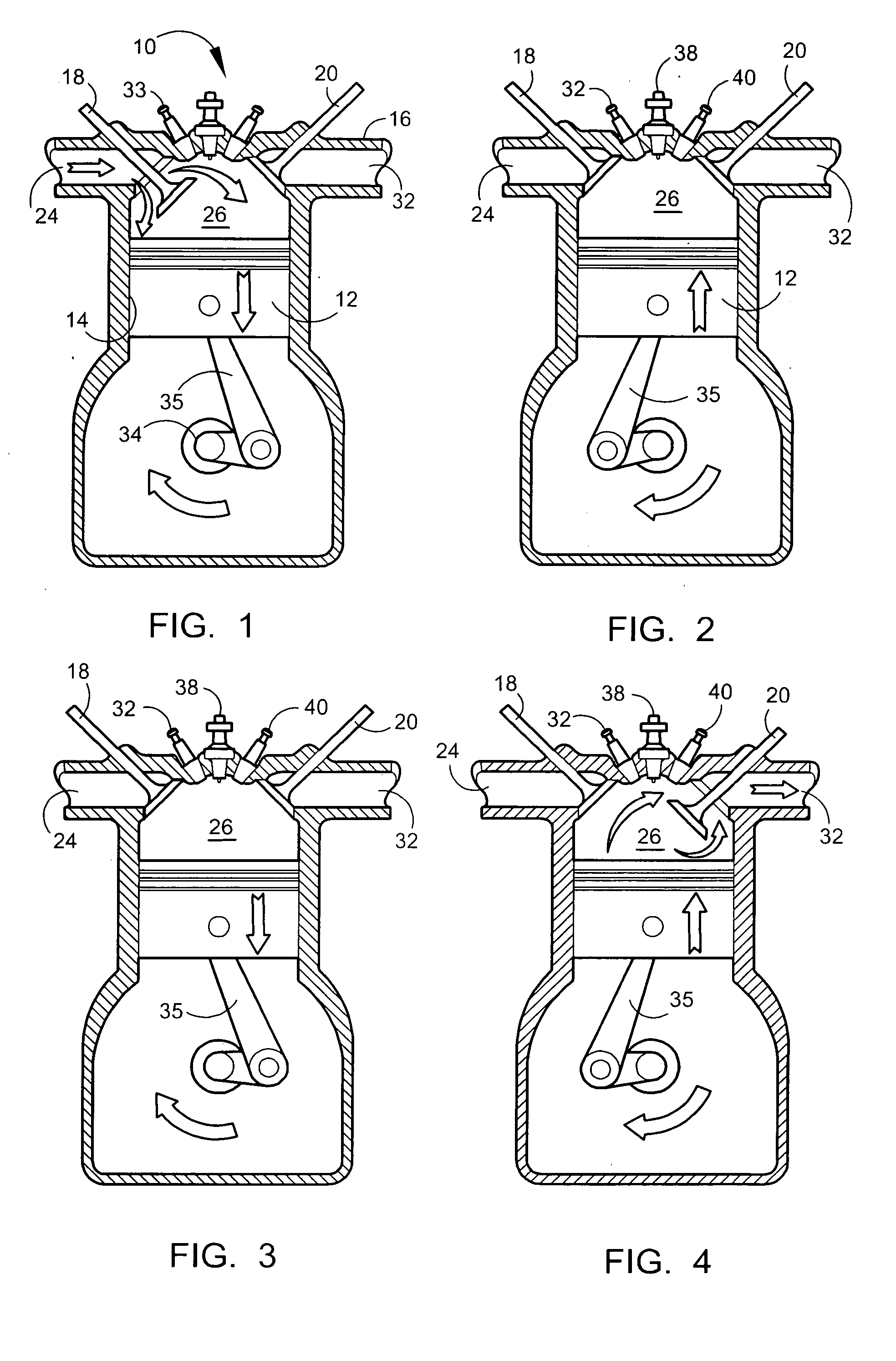
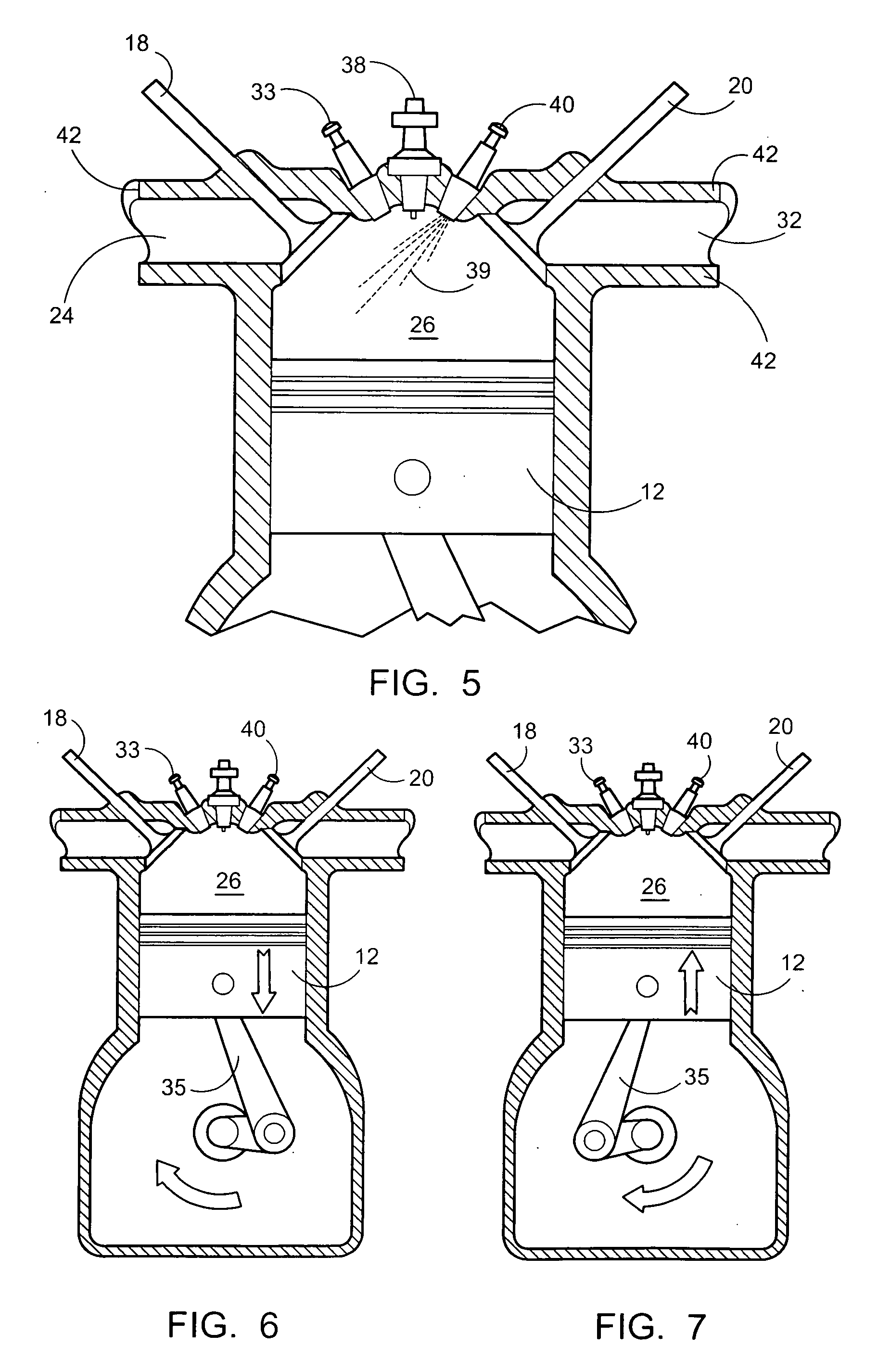
[0058] As shown in FIGS. 1-10 the device employs a novel manner to both cool and increase the power and economy of an internal combustion engine through a recapture of waste heat. In FIG. 1 there is shown a side sliced view of a piston 12 positioned toward an upper position in the cylinder 14 adapted for reciprocated engagement with the piston 12. During a conventional intake stroke of a two or four-cycle engine, the piston 12 moves away from the cylinder head 16 which provides the engagement point for the intake valve 18 and the exhaust valve 20. The intake valve translates to open and close the valve head portion 21 in a seat 22. The intake valve 18 thus controls communication of the intake manifold 24 with the combustion chamber 26. Likewise the exhaust valve 20 translates to engage and disengage a head portion 28 with an exhaust seat 30 and control communication of the combustion chamber 26 with the exhaust manifold 32.

[0059] Conventionally, fuel is communicated to the combusti...


PUM


Abstract

An internal combustion engine and method of operation employing timed injection of water into the combustion chamber for one or a combination of recapturing waste heat, cooling the engine, and lowering Nox emissions of the engine. The water injection subsequent to the power stroke of the engine employs residual heat and heat conducted from surfaces of the combustion chamber, to form steam to drive a second power stroke. The water injection can also be employed to pre-cool the combustion chamber to avoid formation of Nox gases during fuel combustion and by recapturing residual and conductive heat from the combustion chamber the engine is cooled thereby minimizing or eliminating exterior cooling system requirements.

Description

BACKGROUND OF THE INVENTION [0001] 1. Field of the Invention [0002] This application claims priority from U.S. provisional application Ser. No. 60 / 703,394, filed Jul. 27, 2005. The present invention relates to internal combustion engines. More particularly it relates to apparatus and method of operation of an internal combustion engine for timed injection of water into a cylinder which can be employed for one or a combination of recapturing waste heat, cooling the engine, and lowering NOX emissions, by providing an extra power stroke to the engine from the expansion of the water into steam which also cools the engine internally. The design and method of operation of the device are suitable for use on any type of internal combustion engine using any type of fuel for the fuel / air mixture be it gasoline, diesel, Wankel, or other engine employing combustion of fuel to produce work from recaptured waste heat as well as a means to internally cool the engine on which it is employed to redu...

Claims


Application Information

Patent Timeline
IPC IPC(8): F01B29/04
CPCF02B47/02F02M25/03F02M25/0222Y02T10/16F02M25/0227Y02T10/121Y02T10/12
Inventor CROWER, H. BRUCE
Owner CROWER H BRUCE
Why Eureka
Try Eureka