
Temperature exchanging element made by extrusion, and its applications

a technology of temperature exchange element and extrusion, which is applied in the field of thermal exchange and radiation energy collection device, can solve the problems of inability to modify the appearance, arrangement or dimensions of the radiator, and inability to envisage the use of another source of heat, etc., and achieves the effects of low cost, simple and rapidity, and high efficiency of the temperature exchange elemen

Inactive Publication Date: 2007-02-01
CALORIGEN USA CORP
View PDF12 Cites 7 Cited by
  • Summary
  • Abstract
  • Description
  • Claims
  • Application Information

AI Technical Summary

Benefits of technology

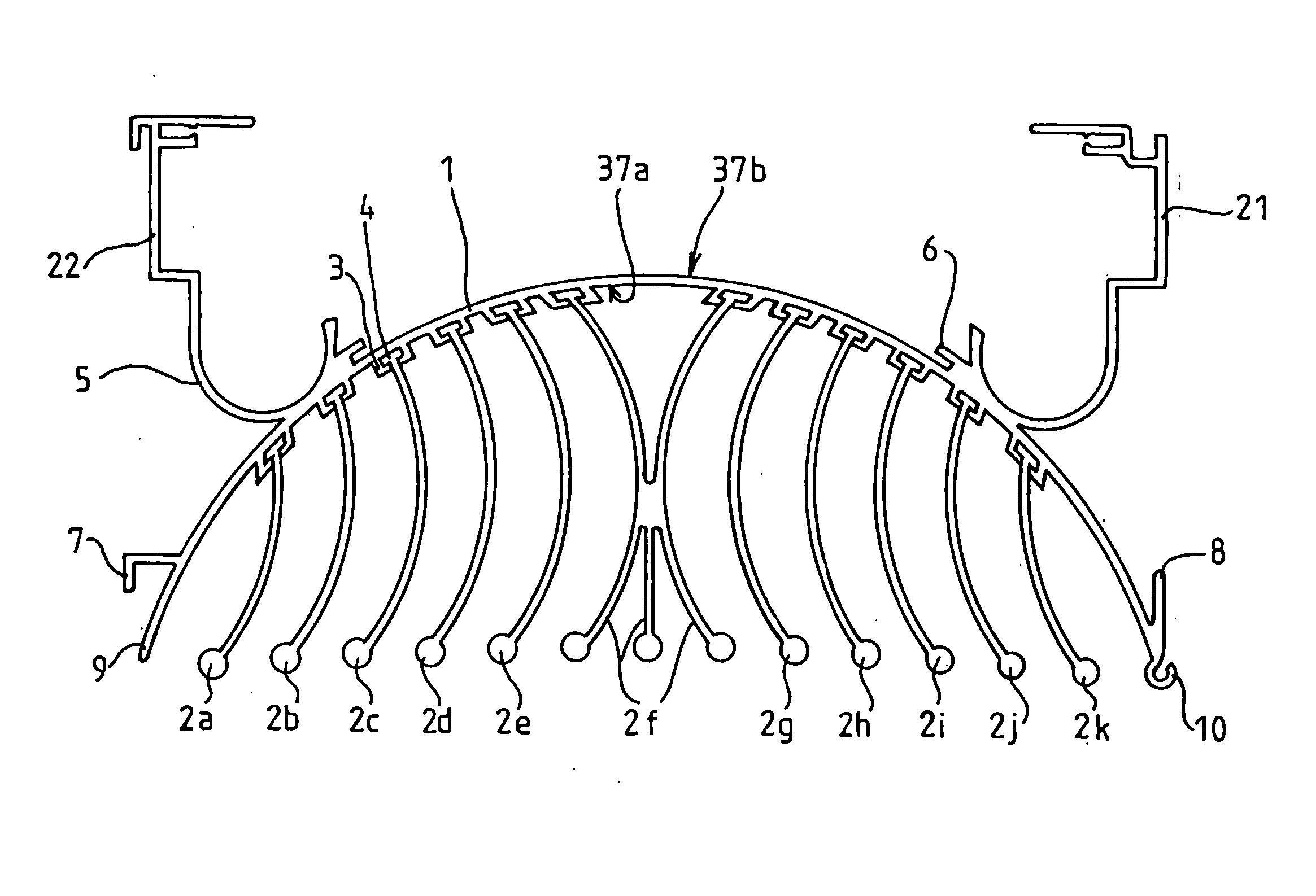
[0026] The fins have a corrugated profile so as to increase the heat exchange surface.
[0041] Another advantage lies in the fact that the invention enables the diffusion of heat to be eliminated by the stratification of hot air at ceiling height thereby reducing energy consumption.

Problems solved by technology

This radiator, however, suffers from several drawbacks.
A first drawback lies in the fact that this radiator is exclusively designed to use the circulation of hot water as a heat source.
It is not possible to envisage the use of another source of heat.
Another drawback lies in the fact that the heat diffusion fins are integral with the tubular part of the central body or upper duct.
It is thus impossible for their appearance, arrangement or dimensions to be modified.
At the moment, however, few systems exist which fulfill both heating and cooling functions for a room.
A first drawback lies in the cost of manufacture and installation.
Another drawback lies in the fact that a flow of air often generates medical problems for the users (development of germs in the system, chills, etc.).
Another drawback lies in the poor efficiency of these energy-consuming systems.

Method used


Image

  • Temperature exchanging element made by extrusion, and its applications
  • Temperature exchanging element made by extrusion, and its applications
  • Temperature exchanging element made by extrusion, and its applications

Examples


Embodiment Construction

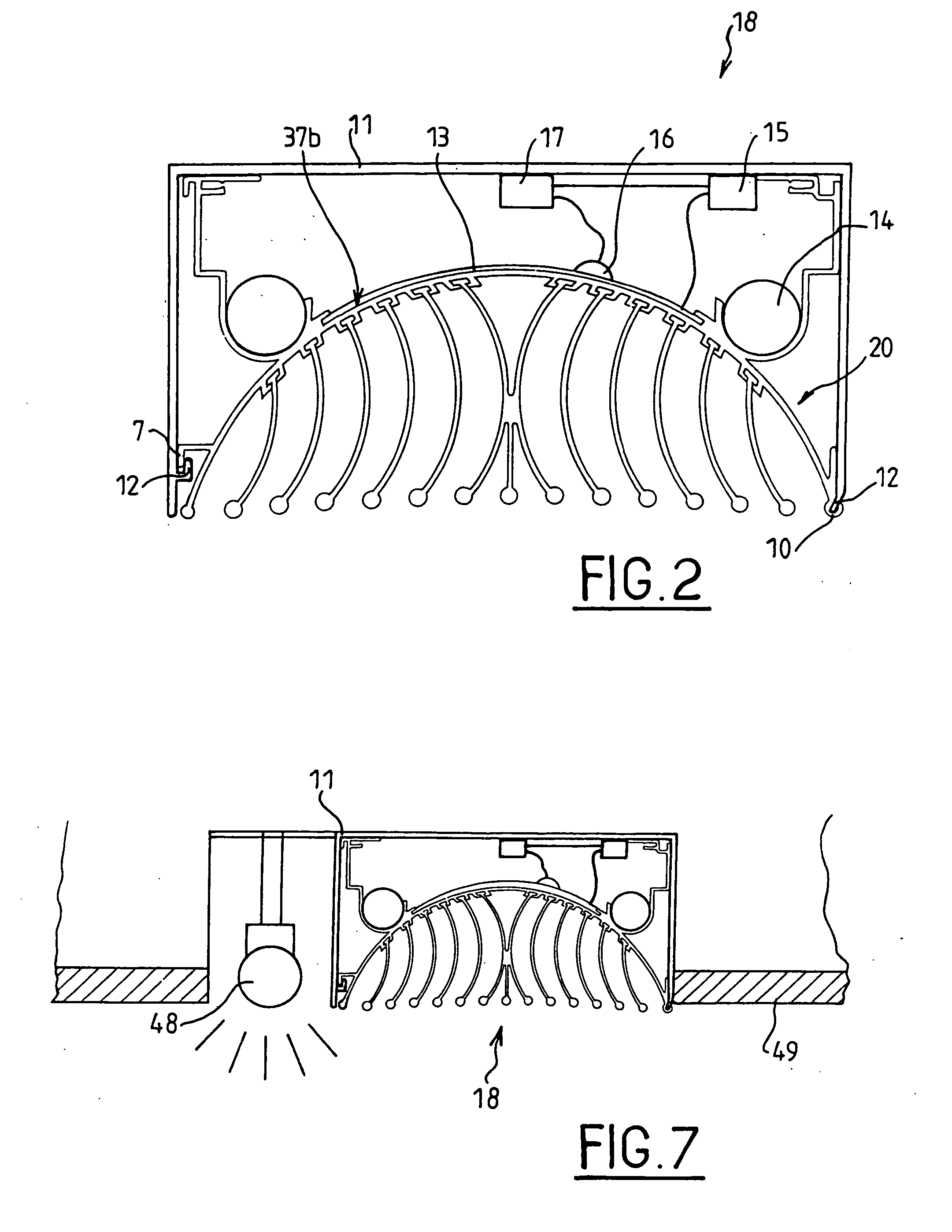
[0053] The operating principle implemented in the temperature exchanging element according to the invention is that of the use of a reduced ΔT (temperature difference) between the temperature production source and the source of use, thereby inducing a substantial improvement in efficiency, and consequently a substantial reduction in energy consumption. The temperature-exchanging element may be used in radiator mode to warm a room or in evaporator mode to reduce the temperature in a room.

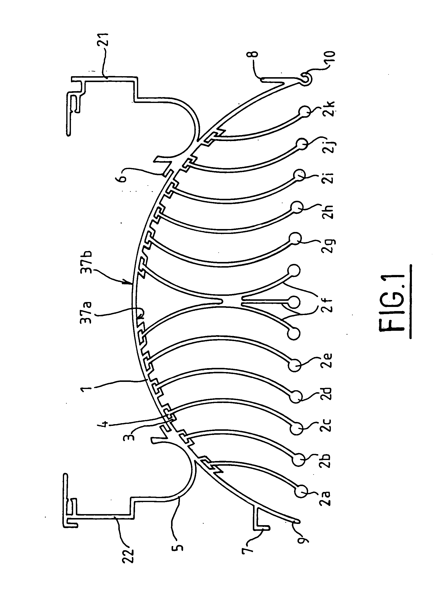
[0054]FIG. 1 shows a top view of a temperature-exchanging element 20 according to the invention. In this embodiment, the temperature-exchanging element 20 incorporates a single-piece extruded base 1 onto which heat-exchanging fins 2a to 2k made by extrusion are attached. The single-piece base 1 has an external face 37a provided with guide rails 3 constituting reception means for the radiation fins and an inner face 37b provided with means 6 to integrate a heating element and means 5 to integrate a h...


PUM

PropertyMeasurementUnit
lengthaaaaaaaaaa
widthaaaaaaaaaa
widthaaaaaaaaaa

Abstract

The invention relates to a temperature exchanging element made by extrusion and able to receive a heating element and / or heat conducting element, and radiation fins. It is constituted of a single-piece base incorporating an external face equipped with means to receive the radiation fins, and an inner face equipped with at least one means to integrate the heating and / or heat conducting element, said reception and integration means being made during the extrusion of the base. Application to the manufacture of a radiation module, a dryer, an air conditioner, a solar energy collection device.

Description

BACKGROUND OF THE INVENTION [0001] 1. Field of the Invention [0002] The technical sector of the present invention is that of thermal exchange and radiation energy collection devices, and more particularly heating, cooling and solar radiation collection devices. [0003] 2. Description of the Related Art [0004] Heating and maintaining a constant temperature in a room or building is a principal concern for architects and heating engineers who must plan for and provide one or several heating sources according to the geometry of the room to be heated. Numerous means to heat a room are known: floor heating, forced-air heating, convector heating, and radiant heating or a combination of convection and radiant heating. Radiators are currently the most common heating means. They are classically produced by molding in cast iron, steel or aluminum. The heating elements in a radiator are generally made by the circulation of hot air through piping or by electrical resistance. [0005] New extrusion ...

Claims


Application Information

Patent Timeline
Patent Type & Authority Applications(United States)
IPC IPC(8): C03C15/00B44C1/22C03C25/68C23F1/00
CPCF24D3/165F24H3/002F24J2/0494F21V33/0092F28F3/02Y02E10/44F28F2255/16F24J2/26F24S70/65F24S10/75Y02B30/00
Inventor BOUSSIER, JEAN-JACQUES
Owner CALORIGEN USA CORP
Learn More