
Production method of acoustic diaphragm, acoustic diaphragm, and speaker

a production method and diaphragm technology, applied in the direction of electric/magnetic/electromagnetic heating, electrical transducers, induction heating, etc., can solve the problems of difficult to obtain a practical strength over a long term as a speaker diaphragm, easy to break the workpiece, etc., to reduce the deformation of the diaphragm shape, reduce the cost, and high the effect of carbonization ratio

Inactive Publication Date: 2007-02-01
VICTOR CO OF JAPAN LTD
View PDF0 Cites 13 Cited by
  • Summary
  • Abstract
  • Description
  • Claims
  • Application Information

AI Technical Summary

Benefits of technology

[0018] The present invention has been achieved in view of the above problems, and it is an object of the invention to reduce deformations of a diaphragm shape such as warpage and contortion at an impregnation step of resin and at a burning step during the production process of an acoustic diaphragm having a high carbonization ratio, and to reduce cost and to enhance mass productivity.
[0022] According to the present invention, since the deformations such as warpage and contortion during the impregnation step of resin and the burning step can be reduced, the precision of assembling the speaker is enhanced, thereby improving the speaker vibration characteristics which are conventionally deteriorated due to poor assembling precision.
[0023] According to the present invention, a press is not required when the workpiece is burned, the workpiece can be burned with high mechanical precision only by putting the workpiece into a baking furnace, and it is possible to enhance the productivity and to reduce cost.
[0024] A step of subjecting at least a portion of a surface of the workpiece to an air-leakage preventing processing to close a fine hole formed in the workpiece is provided after the step of carbonizing the organic matter. With this configuration, it is possible to prevent air at a front surface of the diaphragm from leaking toward the back surface of the diaphragm and to prevent air at the back surface of the diaphragm from leaking toward the front surface of the diaphragm. Thus, a basic performance as the acoustic diaphragm can be obtained easily.
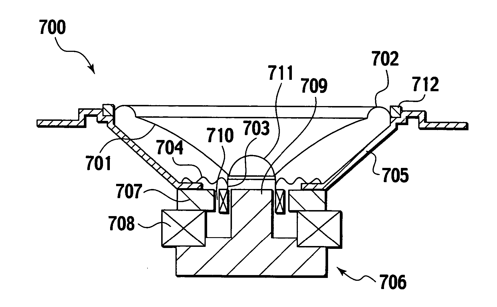
[0026] At the step of forming the workpiece, in order to make a size of the workpiece become equal to a predetermined size after the burning, the workpiece is formed such that a size reduced by contraction at the time of burning is added to the predetermined size. With this configuration, it is possible to make the inner diameter of a hole at the center of the acoustic diaphragm and the outer diameter of a bobbin of a voice coil substantially equal to each other. Therefore, in assembling the speaker, it is possible to prevent an adhesive from excessively entering between the voice coil bobbin and the center of the acoustic diaphragm, and to avoid a case where the voice coil can not be inserted into the center of the acoustic diaphragm.
[0027] At the step of forming the workpiece, the workpiece is formed by milling and drying the workpiece in a nonpressurized state. With this, the thickness of the completed workpiece is increased while keeping flexibility thereof, the workpiece becomes strong against external force, and the mechanical strength is increased. Further, the acoustic diaphragm has high rigidity which is essential for acoustic diaphragms, and accordingly it is possible to provide a speaker having excellent acoustic properties.

Problems solved by technology

The reason why the solution including the phenol resin is impregnated into the workpiece formed using the natural material is that the workpiece is prone to be broken if it is formed only of the natural material including the organic matter, and it is difficult to obtain a practical strength over a long term as a speaker diaphragm.

Method used


Image

  • Production method of acoustic diaphragm, acoustic diaphragm, and speaker
  • Production method of acoustic diaphragm, acoustic diaphragm, and speaker
  • Production method of acoustic diaphragm, acoustic diaphragm, and speaker

Examples


Embodiment Construction

[0047] Embodiments of the present invention will be explained below.

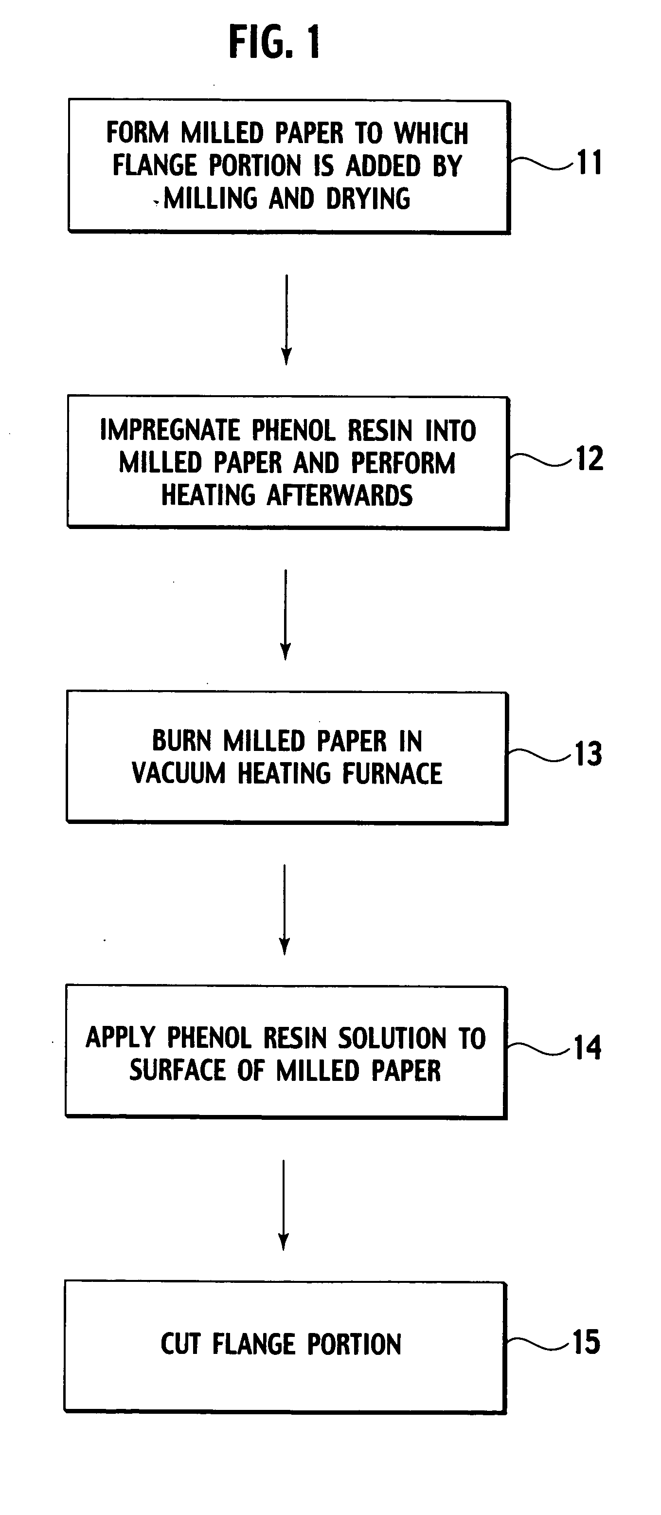
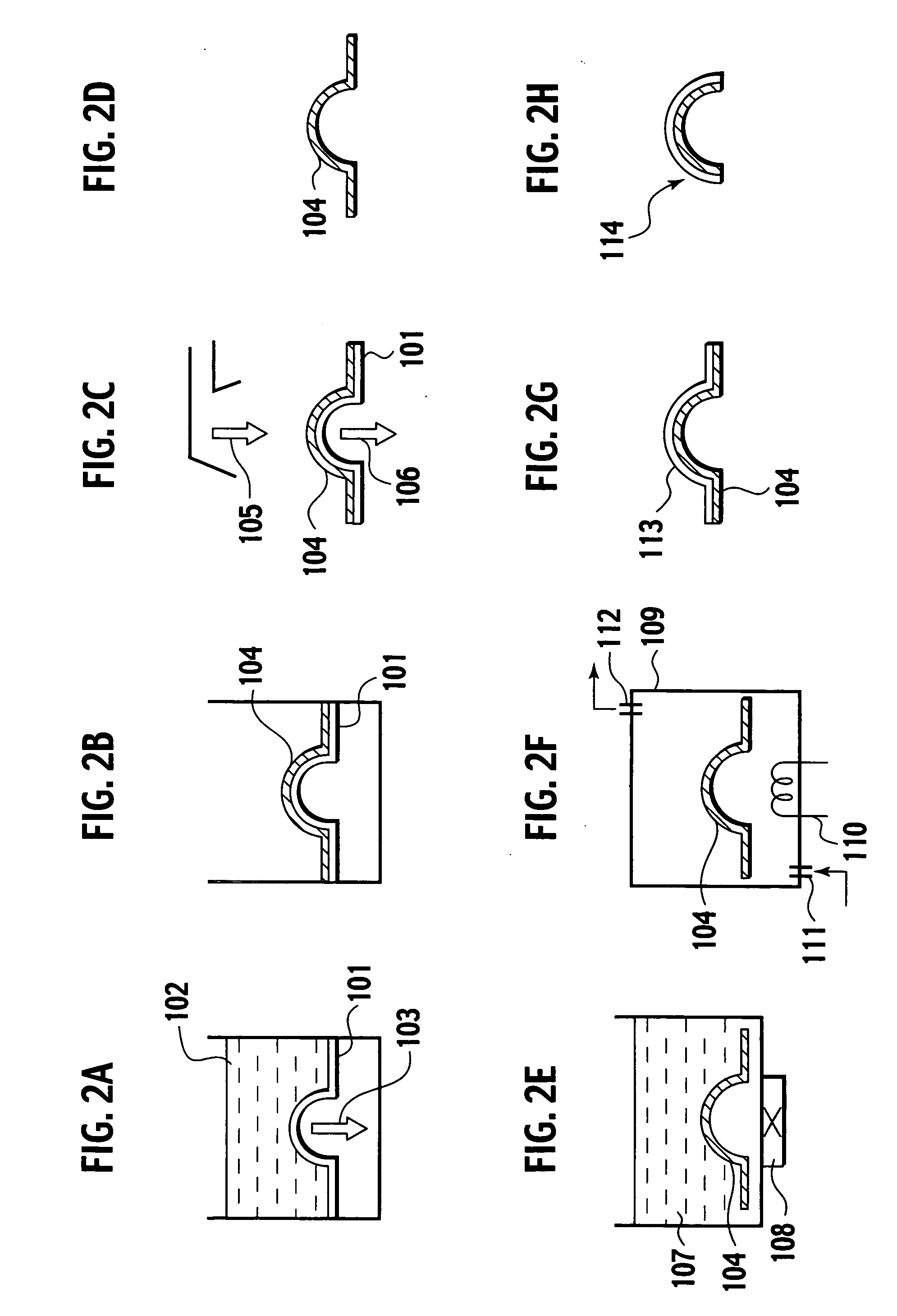
[0048] A first embodiment of the present invention will be explained first. FIGS. 1 and 2A to 2H are explanatory diagrams of a production method according to the first embodiment.

[0049] At a first step 11 in FIG. 1, as shown in FIG. 2A, a center portion is previously formed into a domical shape (hemispherical shape), a mesh 101 provided at its domical shape periphery with a flat (flange) portion is prepared (since the workpiece contracts by a burning operation, the mesh is formed larger than the size of the workpiece after the burning operation. For example, when it is heated at 800° C., contraction of, for example, 25% is taken into consideration, and the mesh is formed larger by this value). The mesh 101 is put into dispersion liquid 102 into which mixture fiber of 90 wt % of linter (cotton fiber) 10 wt %+NBKP [Needle Bleach Kraft Pulp] (softwood fiber is made into pulp by kraft process and is further exposed) i...


PUM


Abstract

A production method of an acoustic diaphragm including the steps of: forming an acoustic diaphragm-shaped workpiece with a flange portion added to at least a portion of an outer periphery of the workpiece by using a natural material including an organic matter which can be carbonized by burning; impregnating a solution including phenol resin into the workpiece obtained at the above step, and then heating the workpiece to a predetermined temperature to bring the phenol resin into a high polymer state; and burning the workpiece processed at the above step under a substantially anoxic atmosphere to carbonize the organic matter.

Description

BACKGROUND OF THE INVENTION [0001] 1. Field of the Invention [0002] The present invention relates to a method of producing a porous acoustic diaphragm having a high carbonization ratio, an acoustic diaphragm, and a speaker using the acoustic diaphragm. [0003] 2. Description of the Related Art [0004] As an acoustic diaphragm for a speaker that outputs clear sound with small distortion, a porous diaphragm having a high carbonization ratio attracts attention in terms of the extent of internal losses. [0005] However, in a production method of a diaphragm having a high carbonization ratio by burning a natural diaphragm material having various organic matters at a high temperature to carbonize the organic matters, deformations such as warpage and contortion as well as fracture are prone to be generated in the diaphragm at a resin impregnating step or at a burning step during the production process, and prevention thereof is a major technical issue. [0006] The deformations such as warpage ...

Claims


Application Information

Patent Timeline
Patent Type & Authority Applications(United States)
IPC IPC(8): H05B6/10
CPCH04R31/003
Inventor SUZUKI, YOSHIAKITANAKA, YOSHIAKI
Owner VICTOR CO OF JAPAN LTD
Learn More