RFID tag and manufacturing process thereof

a technology of RFID tags and manufacturing processes, applied in the field of RFID tags, can solve the problems of low reliability, large number of parts, and no improvement in regard to achieving improvement, and achieve the effects of reducing manufacturing steps, high reliability, and reducing thickness

Inactive Publication Date: 2007-02-01
RICOH KK
View PDF4 Cites 45 Cited by
  • Summary
  • Abstract
  • Description
  • Claims
  • Application Information

AI Technical Summary

Benefits of technology

[0061] According to the present invention, it becomes possible to provide a highly reliable R

Problems solved by technology

However, even when the antenna coil disclosed in Patent Reference 1 is used, there is achieved no improvement with regard to the problem of large number of parts and large number of assembling steps or low reliability of the connection

Method used


Image

  • RFID tag and manufacturing process thereof
  • RFID tag and manufacturing process thereof
  • RFID tag and manufacturing process thereof

Examples


first embodiment

[0076] Hereinafter, explanation will be made on a first embodiment of the present invention.

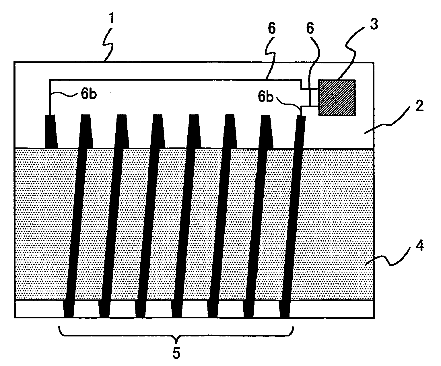
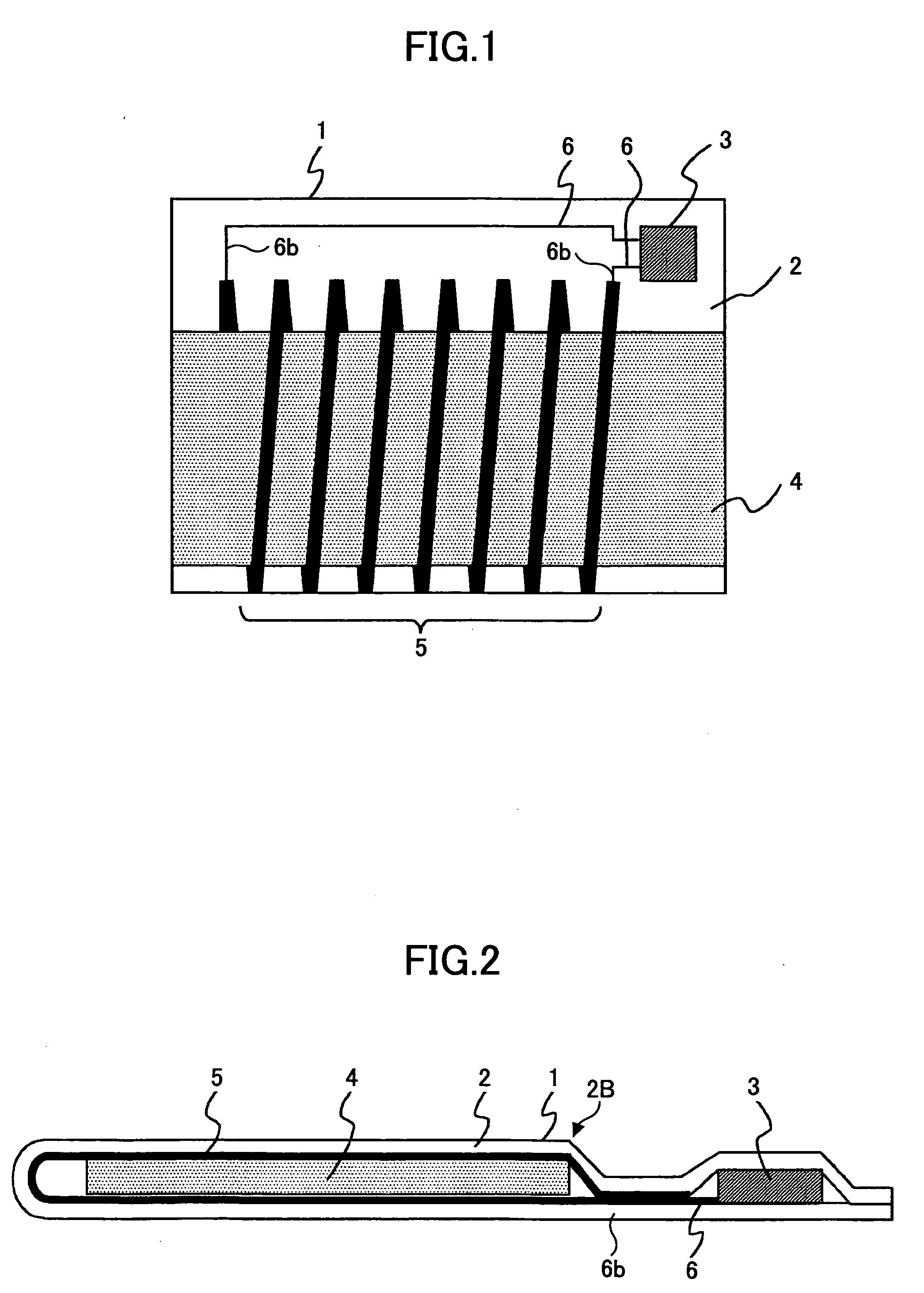
[0077]FIG. 1 shows the construction of an RFID 1 of to the present embodiment, while FIG. 2 shows the cross-sectional structure of the RFID tag 1.

[0078] Referring to FIGS. 1 and 2, the RFID tag 1 includes an insulation sheet 2, a semiconductor chip 3, a magnetic core member 4, a coil pattern 5 and an interconnection pattern 6, wherein the coil pattern 5 and the semiconductor chip 3 are formed on the same side of the insulation sheet 2, and the insulation sheet 2, carrying thereon the coil pattern 5, covers the semiconductor chip 3 and wraps around the magnetic core member 4.

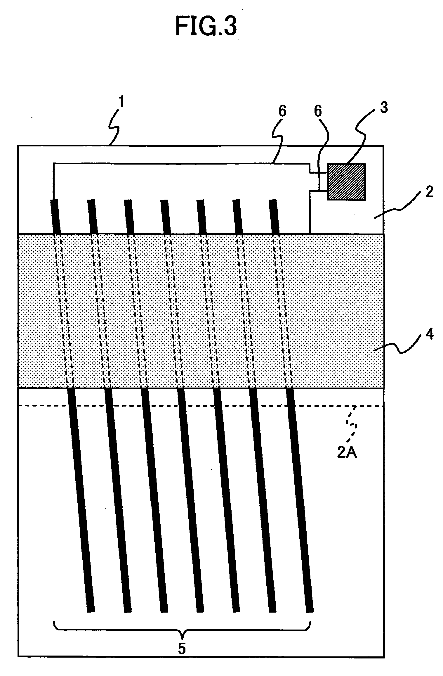
[0079]FIG. 3 shows the RFID tag 1 in the state before completion of the assembling.

[0080] Referring to FIG. 3, it can be seen that there are formed parallel, bar-shaped conductor patterns forming together a coil pattern 5 on one side of the insulation sheet 2, and another conductor pattern forming the interconnection p...

second embodiment

[0099] Next, a second embodiment of the present invention will be explained, wherein those parts corresponding to the parts described previously are designated by the same reference numerals and the description thereof will be omitted.

[0100]FIG. 4 shows the construction of an RFID tag according to the present embodiment, while FIG. 5 shows the cross-section of the RFID tag of the present embodiment.

[0101] Referring to FIGS. 4 and 5, the RFID tag of the present embodiment has a generally identical construction to the RFID tag of the first embodiment, except that the insulation sheet 2 is now formed of a lower insulation sheet 2A and an upper insulation sheet 2B.

[0102] Thus, with the present embodiment, the coil pattern 5 is also divided into a lower coil pattern part 5A provided on the lower insulation sheet 5A and an upper coil pattern part 5B provided on the upper insulation sheet 5B.

[0103] Assembling of the RFID tag 1 of the present embodiment is conducted similarly to the cas...

third embodiment

[0105] Next, a third embodiment of the present invention will be described.

[0106]FIG. 7 shows the construction of the RFID tag according to the third embodiment of the present invention, wherein those parts corresponding to the parts described previously are designated by the same reference numerals and the description thereof will be omitted.

[0107] Referring to FIG. 7, the RFID tag of the present embodiment has a construction similar to that of the RFID tag of the second embodiment, except that there is provided a thermal paper 19 on a flat surface of the RFID tag via an adhesion layer 18.

[0108] Here, it should be noted that the thermal paper 19 is a rewritable thermal paper while the adhesive layer 18 may be formed by applying a sticking layer or a both-side adhesive film.

[0109] With the use of such a rewritable thermal paper 19, in which the part applied with heat changes dark, it is possible to represent or display characters or images by using a thermal print head. Further,...


PUM


Abstract

An RFID tag comprises a semiconductor chip storing therein information of an object to be discriminated and carrying out radio communication with a reader/writer device; and an antenna coil provided with a magnetic core member and connected electrically to the semiconductor chip. The semiconductor chip and the magnetic core member are wrapped by an insulation sheet carrying an interconnection pattern connecting a pad of the semiconductor chip and the antenna coil electrically and plural coil patterns on one side thereof. The plural coil patterns includes bar-shaped conductor patterns formed obliquely to the magnetic core member, each of the bar-shaped conductor patterns having an end connected to an end of an adjacent coil pattern, the bar-shaped conductor patterns thereby forming together a spiral coil around the magnetic core member. The coil patterns being connected with each other at a part where the coil patterns overlap with each other.

Description

[0001] The present invention generally relates to RFID tags, and more particularly to an RFID tag capable being formed with reduced thickness, assembled with fewer number of steps and capable of providing reliable electric connection. Further, the present invention provides the manufacturing process thereof. [0002] In view of compact size and low cost and further in view of the capability of handling overwhelmingly large amount of information, RFID tags are used in various products and goods in recent years. [0003] An RFID tag includes a memory area allowing reading and writing via a reader / writer device. Typically, this memory are is used to store various discrimination information of the object, such as model number, price, date of manufacture, usable period, guarantee period, recycle information, and the like. [0004] Such information is written and read out by a reader / writer device. [0005] Because RFID tags are used in a wide variety of objects, there is a demand of compact size...

Claims


Application Information

Patent Timeline
IPC IPC(8): G06K7/00
CPCG06K19/07749H01L2224/16H01L2224/32225H01L2224/48091H01L2224/48227H01L2224/73265H01L2224/8592H01L2924/00014H01L2924/00H01L2924/00012H01L24/73
Inventor TAN, KUNIHIROYONEDA, KAZUHIRO
Owner RICOH KK
Why Eureka
Try Eureka