Sample measuring device

a measuring device and sample technology, applied in the direction of material analysis using wave/particle radiation, instruments, nuclear engineering, etc., can solve the problems of difficult to adjust the position of the area within the focal point of the light collecting mirror part, complicated and enlarged measuring devices, and troublesome movement and adjustment of the position adjusting mechanism

Inactive Publication Date: 2007-02-01
HORIBA LTD
View PDF12 Cites 35 Cited by
  • Summary
  • Abstract
  • Description
  • Claims
  • Application Information

AI Technical Summary

Problems solved by technology

However, conventionally the axis of the electron beams has to be set inside the path and a position adjusting mechanism to move and adjust the light collecting mirror part is necessary in order to set the position on which the electron beams are irradiated within the focal point, thereby to make the measuring device complicated and enlarged.
In addition, if the position adjusting mechanism is used, there is a problem that it becomes very troublesome to move and adjust the position adjusting mechanism.
Especially, in case of using a high-resolution scanning electron microscope, since an area on which the electron beams are irradiated is a minute area less than 10 nanometer, it is very difficult to adjust a position of the are

Method used


Image

  • Sample measuring device
  • Sample measuring device
  • Sample measuring device

Examples


first embodiment

[0035] A first embodiment of the present claimed invention will be explained with reference to drawings.

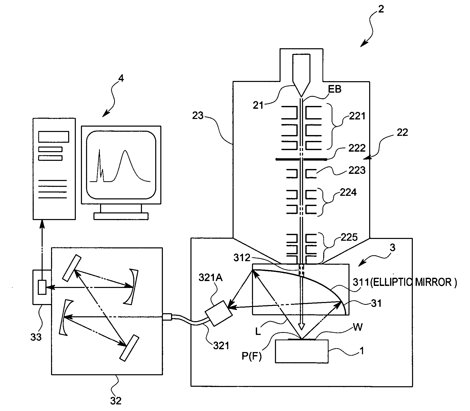
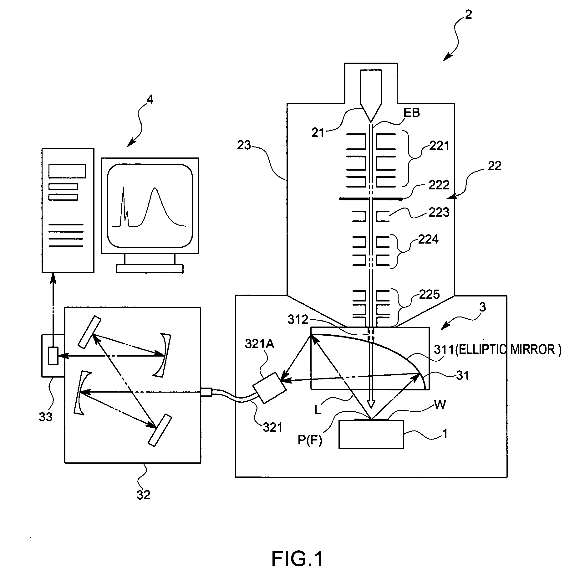
[0036] A sample measuring device (hereinafter called as an electron beam measuring device) in accordance with this embodiment makes an evaluation on physicality in a minute area of a sample W or makes an analysis on a semiconductor element by the use of light L (cathode luminescence) generated from the sample W by irradiating electron beams EB as being energy beams on the sample W, and comprises as shown in FIG. 1, a sample stage 1, an electron beam irradiation device 2 that irradiates the electron beams EB as being the energy beams on the sample W placed on the sample stage 1, a sensing device 3 as being a light sensing part that divides and detects the luminescence L generated from the sample W due to irradiation of the electron beams EB, and an information processing unit 4 that receives an output signal from the sensing device 3 and that conducts a predetermined arithmetic co...

second embodiment

[0056] Next, a second embodiment in accordance with this invention will be explained with reference to drawings. An identical code is given to a component corresponding to the first embodiment.

[0057] As shown in FIG. 4, a sample measuring device in accordance with this embodiment is different from the first embodiment in arrangements of the sensing device 3 and the electron beam irradiation device 2.

[0058] More specifically, the sensing device 3 in the first embodiment comprises the light collecting mirror part 31, however, in this embodiment a electron optical column part 23 of the electron beam irradiation device 2 has the light collecting mirror part 31.

[0059] The electron beam irradiation device 2 in accordance with this embodiment is, for example, of a scanning type and comprises, an electron gun 21 as being an energy beam generating part, an energy beam control device 22 comprising a lens mechanism to converge the electron beams EB irradiated from the electron gun 21 on a m...


PUM


Abstract

An object of this invention is to make it easy to adjust a position of the energy beam to irradiate and a position of a focal point of a light collecting mirror part, and to prevent displacement of the light collecting part due to vibration with a simple arrangement. A sample measuring device in accordance with this invention is to measure light generated from a sample W by irradiating electron beams EB on the sample W, and comprises a electron optical column part 23 that converges the electron beams EB, and a light collecting mirror part 31 that is arranged between the electron optical column part 23 and the sample W and that has an energy beam path 312 to pass the electron beams EB converged by the electron optical column part 23 and to irradiate the electron beams EB on the sample W and a mirror face 311 whose focal point F is set on an axis of the energy beam path 312 and that collects the light L generated from the sample W by means of the mirror face 311, wherein the light collecting mirror part 31 is supported by the electron optical column part 23 so that the axis of the electron beams EB coincides with the focal point F.

Description

FIELD OF THE ART [0001] This invention relates to a sample measuring device that measures light generated by irradiating energy beams on a sample. BACKGROUND ART [0002] There is a sample measuring device (an optical measuring device) of this kind that makes an evaluation on physicality in a minute area of a sample or an analysis on a semiconductor element by the use of light (cathode luminescence) generated from the sample by irradiating electron beams on the sample. [0003] The sample measuring device has an arrangement, as shown in the patent document 1, wherein an image is formed on an optical fiber or an entrance slit of a spectroscope arranged outside of an electron microscope by arranging a light collecting mirror part to cover a sample in order to collect cathode luminescence. Since the light collecting mirror part covers the sample, a path to pass the electron beams is arranged in order to irradiate the electron beams on the sample. The light collecting mirror part has to be ...

Claims


Application Information

Patent Timeline
IPC IPC(8): G21K7/00
CPCH01J37/228H01J37/244H01J37/256H01J2237/2808H01J2237/24485H01J2237/24507H01J2237/24585H01J2237/2445
Inventor NISHIKATA, KENTAROSAIJO, YUTAKAKAKINUMA, SHIGERUAOYAMA, JUNICHIOHASHI, SATOSHI
Owner HORIBA LTD
Why Eureka
Try Eureka