Phase Locked Loop Fast Lock Method

a phase lock and fast lock technology, applied in the direction of pulse automatic control, oscillator tubes, electric devices, etc., can solve the problems of affecting the speed the bandwidth of the pulsing pump, and the inability to meet the numbers, so as to reduce the bandwidth and/or dampen the pulsing

Active Publication Date: 2007-02-01
ZARLINK SEMICON LTD
View PDF24 Cites 32 Cited by
  • Summary
  • Abstract
  • Description
  • Claims
  • Application Information

AI Technical Summary

Benefits of technology

[0019] The method to decrease the settling time and improve the quality of the output clock during the settling in accordance, with the teachings of this invention comprises of the following broad steps:
[0026] In another aspect, the invention provides a method of locking a phase lock loop (PLL) after a lock lost is detected, comprising estimating a new frequency offset using a circuit separate from the PLL; integrator ramping to the new frequency offset; adjusting the phase of the PLL based on the new frequency offset by performing phase build out if a zero phase offset is not required, or performing a phase pull in if a zero phase is required; and decaying the PLL to settle to the frequency jump by relaxing the bandwidth and / or damping of the PLL
[0030] The phase change rate and frequency change rate can be controlled accurately and kept within the limits of the various network standards. For example a maximum frequency change rate of 2.9 ppm / s as specified by Telcordia GR-1244-CORE for a Stratum 2 / 3 / 3E clock.

Problems solved by technology

In many applications, relatively large overshoot and peaking is simply not acceptable.
These numbers cannot be met without special measures like temporarily increasing the bandwidth, decreasing the damping or both.
The disadvantage of increasing the PLL's bandwidth is that more phase noise that may be present on the input signal is not attenuated as much before propagating to the output of the PLL.
Decreasing the damping of the PLL will cause a larger overshoot on the output signal.
These effects degrade the quality of the output signal or may even cause disruptions in the network and are therefore undesirable.
However, this method is sensitive to wander and jitter on the input reference clock and can therefore copy a relatively large frequency error to the integrator.
Phase noise (wander and jitter) on the measured reference can degrade the accuracy of the measured frequency offset.
If the PLL uses the same local oscillator clock to generate its output clock, the accuracy of the local clock is a common mode error for both the reference monitor's frequency estimate and the PLL's frequency offset.

Method used


Image

  • Phase Locked Loop Fast Lock Method
  • Phase Locked Loop Fast Lock Method
  • Phase Locked Loop Fast Lock Method

Examples


Embodiment Construction

[0042] Broadly, the method to decrease the settling time and improve the quality of the output clock during the settling disclosed in this patent comprises of the following steps: estimate the new frequency offset, integrator ramp to the new frequency offset, phase build-out or phase pull-in, decay interval, and switch to higher bandwidth and / or lower damping to let the PLL settle.

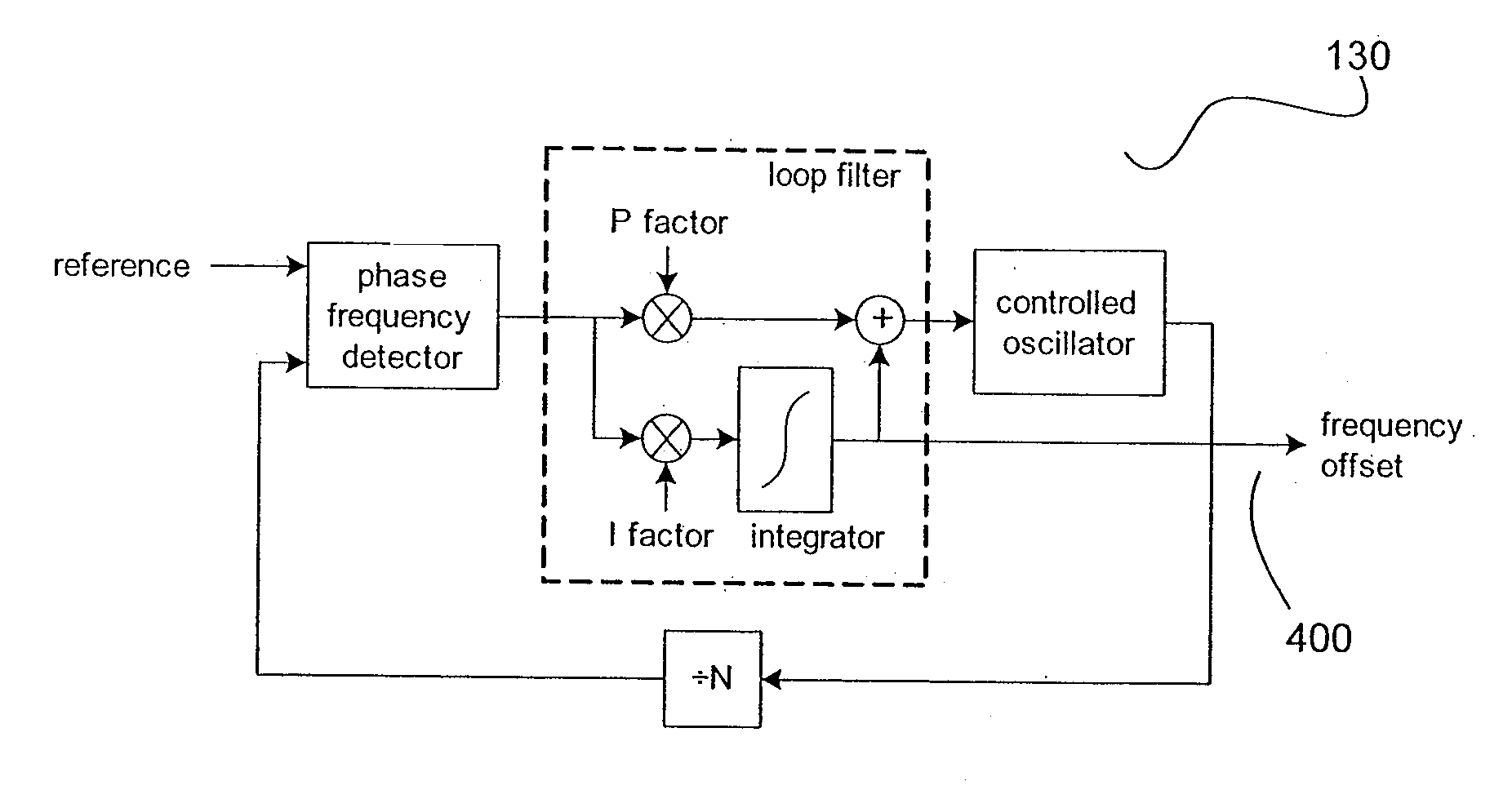
[0043]FIG. 4 illustrates a PLL in accordance with teachings of this invention. A phase and frequency detector 100 outputs to an adder 110 and also to register 112, which is controlled by control unit 114. The output of register 112 is connected to adder 110. The register 112 is a preferred embodiment of a phase build out circuit as described in detail below. The output of adder 110 is. connected to comparator 118. The output of adder 110 is also connected to a pair of multipliers 120, 180, introducing the P and I factors respectively. The multiplier 120 is connected to the first input of adder 140 whose o...


PUM


Abstract

The present invention is a method to rapidly lock a type II phase locked loop (PLL) after a frequency jump without degrading the output signal much. The method to decrease the settling time and improve the quality of the output clock during the settling disclosed herein comprises of the following broad steps: Estimate new frequency offset with a separate circuit outside the PLL loop to measure the frequency of the input signal accurately. Ramp integrator to the new frequency offset. Do phase build out or phase pull-in. The remaining phase offset is build out when no edge to edge alignment is required. Otherwise, the remaining phase offset is pulled in while the integrator in the PLL's loop filter is disabled. Reduce the PLL bandwidth and / or lower damping to let the PLL settle. Switch the PLL to final bandwidth and damping required by the application.

Description

CROSS-REFERENCE TO RELATED APPLICATION [0001] This application claims the benefit of U.S. Provisional Application No. 60 / 703,285 filed Jul. 28, 2005, incorporated by reference herein.FIELD OF THE INVENTION [0002] The invention relates to phase locked loops and in particular a method to achieve lock in a relatively short time. BACKGROUND OF THE INVENTION [0003] One of the. characteristics of a phase locked loop (PLL) is the locking or settling time; i.e. the time it takes the PLL to lock to a certain input signal or to respond to frequency and phase steps. In general, the locking time is dependent on the PLL's loop bandwidth, the lower the loop bandwidth the longer it takes the PLL to lock. It is generally accepted in the art that the term “settle” is defined as arriving within a certain relative or absolute accuracy. [0004] PLLs are not only used in telecommunications applications, but also in measurement technology (for instance optical telemetry), control of motors, medical equipm...

Claims


Application Information

Patent Timeline
Patent Type & Authority Applications(United States)
IPC IPC(8): H03L7/00
CPCH03L7/095H03L7/12H03L7/113H03L7/107Y10S331/02H03L7/1075
Inventor SPIJKER, MENNO TJEERDROSINSKI, JASON ROBERT JR.VAN DER VALK, ROBERTUS LAURENTIUS
Owner ZARLINK SEMICON LTD
Why Eureka
Try Eureka