
Spectroscopy Probe and System for Material Processing Systems

a material processing system and spectroscopy probe technology, applied in the field of near infrared (nir) spectroscopy, to achieve the effect of reducing spectral nois

Inactive Publication Date: 2007-02-01
EXCELITAS TECH
View PDF20 Cites 7 Cited by
  • Summary
  • Abstract
  • Description
  • Claims
  • Application Information

AI Technical Summary

Benefits of technology

[0003] One of the difficulties with monitoring in these process applications is ensuring that the spectroscopy measurements are accurate and repeatable. It is desirable to sample a relatively large area of the processed material since it can be heterogeneous at small scales. Additionally the large area mitigates spectral noise such as from speckle, which is associated with the use of coherent sources such as lasers.

Problems solved by technology

One of the difficulties with monitoring in these process applications is ensuring that the spectroscopy measurements are accurate and repeatable.

Method used


Image

  • Spectroscopy Probe and System for Material Processing Systems
  • Spectroscopy Probe and System for Material Processing Systems
  • Spectroscopy Probe and System for Material Processing Systems

Examples


first embodiment

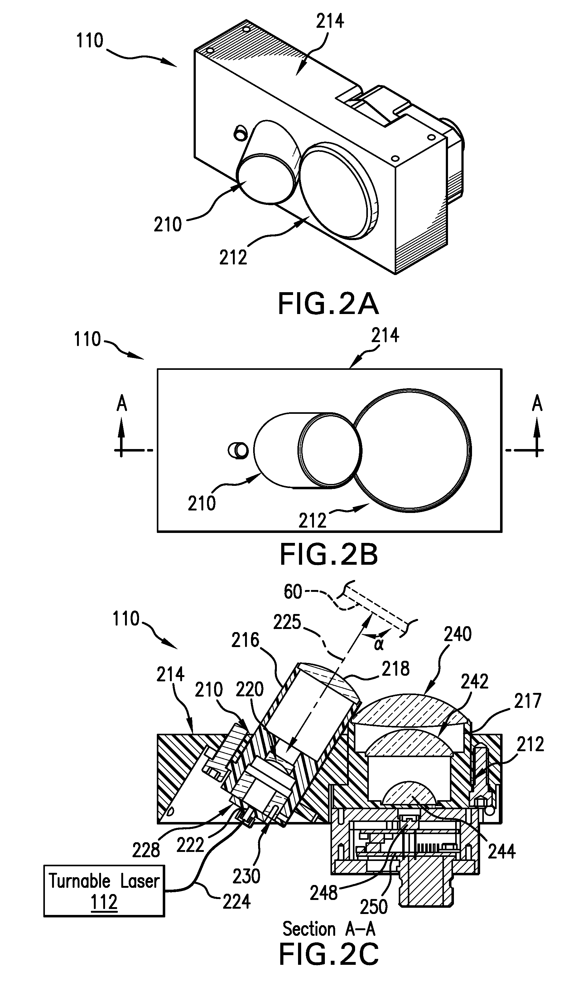
[0030]FIG. 2A is a perspective view of the probe 110. It comprises a projection lens system unit 210 that projects the tunable signal from a laser through the sapphire window 60 to the process material 54. A collection lens system 212 is used to collect the diffusely reflected light from the material 54 and focus it onto a detector. The projection lens system 210 and the collection lens system 212 are located within a housing 214, which is usually bolted or otherwise secured to the drum 50 of the processing system 10.

[0031]FIG. 2B shows the top of the probe 110 with the projection lens system 210, the collection lens system 212, and housing 214.

[0032]FIG. 2C is a cross-sectional scale view of the probe 110 taken along line A-A in FIG. 2B. The projection unit 210 comprises a cylindrical frame 216. This holds an outer convex lens 218 and an inner concave lens 220. An optical input fiber 224 carries the tunable optical signal from the tunable laser 112. These lenses 218, 220 work toge...

second embodiment

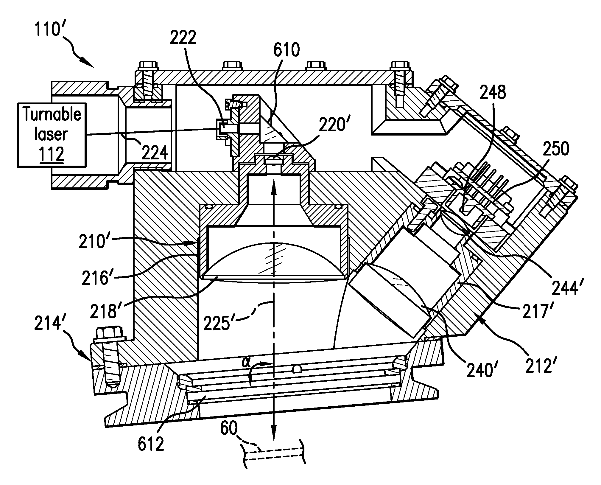
[0044]FIG. 6A is a perspective view of the probe 110′. It similarly comprises a projection lens system that projects the tunable signal from a laser and collection lens system. In this view, they are hidden by the housing 214′, which provides an air sealed arrangement so that the optical assembly can be filled with an inert gas to control spectral noise from water vapor, for example.

[0045]FIG. 6B is a cross-sectional scale view of the probe 110′. The projection unit 210′ of the second embodiment comprises a cylindrical frame 216′ held in housing 214′. This holds outer convex lens 218′ and an inner convex lens 220′. An optical input fiber 224 carries the tunable optical signal from the tunable laser 112 to the output fiber facet in the connector assembly 222. These lenses 218′, 220′ work together to form a collimated beam of the tunable optical signal emitted from a fiber endface / connector assembly 222.

[0046] In the second embodiment 110′, a reflecting prism 610 is used as a fold mi...


PUM


Abstract

A process monitoring system determines a spectral response of a process material. This system has a tunable laser for generating an optical signal that is wavelength tuned over a scan band and an optical probe for conveying the optical signal to the process material and detecting the spectral response of the process material. The optical probe expands a beam of the optical signal to a diameter of greater than 10 millimeters. This avoids one of the difficulties with monitoring these process applications by ensuring that the spectroscopy measurements are accurate and repeatable. It is desirable to sample a relatively large area of the processed material since it can be heterogeneous. Additionally the large area mitigates spectral noise such as from speckle.

Description

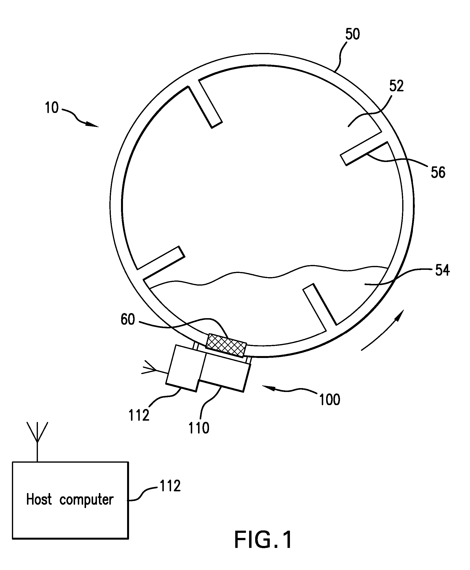
RELATED APPLICATIONS [0001] This claims the benefit under 35 USC 119(e) of U.S. Provisional Application No. 60 / 737,506, filed Nov. 17, 2005, and of U.S. Provisional Application No. 60 / 682,606, filed May 18, 2005, both of which are incorporated herein by this reference in their entirety.BACKGROUND OF THE INVENTION [0002] Spectroscopy, and specifically near infrared (NIR) spectroscopy, has been proposed as a technique for process monitoring in the manufacture of substances, such as pharmaceutical products. For example, in drying applications, e.g., pill drying, the spectroscopy instruments can be used to monitor the water or solvent content during the drying process. This allows the process to be terminated at the optimal time, saving energy and ensuring product uniformity between batches. In blending applications, spectroscopy can be used to monitor the distribution of the active ingredient in the binder material to insure that the processed material is completely admixed and thereaf...

Claims


Application Information

Patent Timeline
Patent Type & Authority Applications(United States)
IPC IPC(8): G01J3/00
CPCG01J3/02G01J3/0208G01J3/4338G01J3/0291G01J3/108G01J3/0286
Inventor ZAMBUTO, JAMESATIA, WALID A.COOK, CHRISTOPHER C.
Owner EXCELITAS TECH
Learn More