Internal combustion engine utilizing hydrogen

a hydrogen-fueled, internal combustion engine technology, applied in the direction of combustion-air/fuel-air treatment, machines/engines, mechanical equipment, etc., can solve the problems of small hydrogen storage amount, low overall energy efficiency, and insufficient hydrogen storag

Inactive Publication Date: 2007-02-08
TOYOTA JIDOSHA KK
View PDF14 Cites 106 Cited by
  • Summary
  • Abstract
  • Description
  • Claims
  • Application Information

AI Technical Summary

Problems solved by technology

In reality, however, the technology concerning a hydrogen supply method is still not established.
However, if the vehicle carries hydrogen that is compressed into a high-pressure tank, the hydrogen storage amount is small because the high-pressure tank has a thick wall and cannot provide an adequate inner volume although the tank is large.
If the vehicle carries liquid hydrogen, the overall energy efficiency is not high because it entails a vaporization loss and requires a large amount of energy for liquefaction.
If the hydrogen storage alloy or hydrogen adsorption material is used, the resulting hydrogen storage density is inadequate and it is very difficult to control hydrogen storage and adsorption.

Method used


Image

  • Internal combustion engine utilizing hydrogen
  • Internal combustion engine utilizing hydrogen
  • Internal combustion engine utilizing hydrogen

Examples


first embodiment

(First Embodiment)

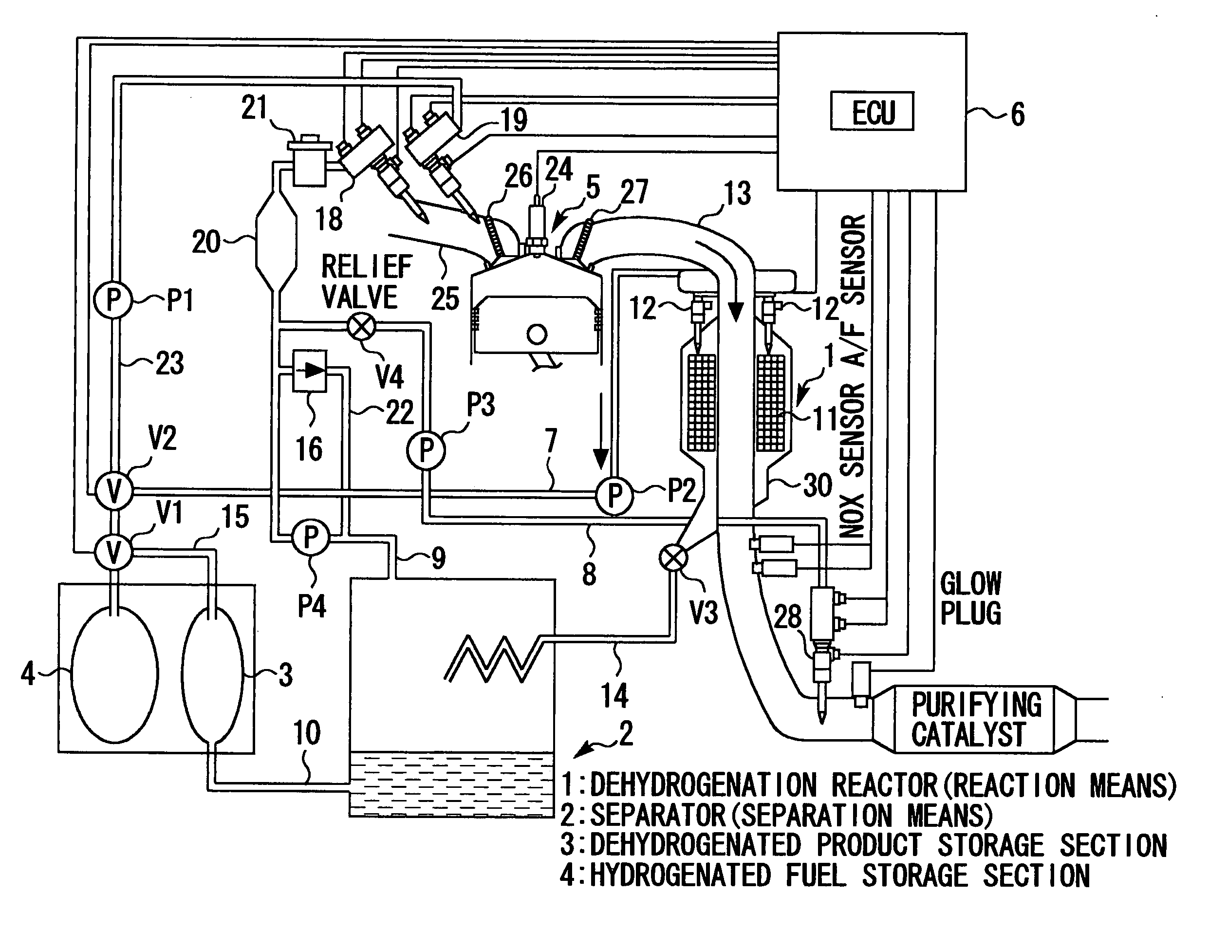
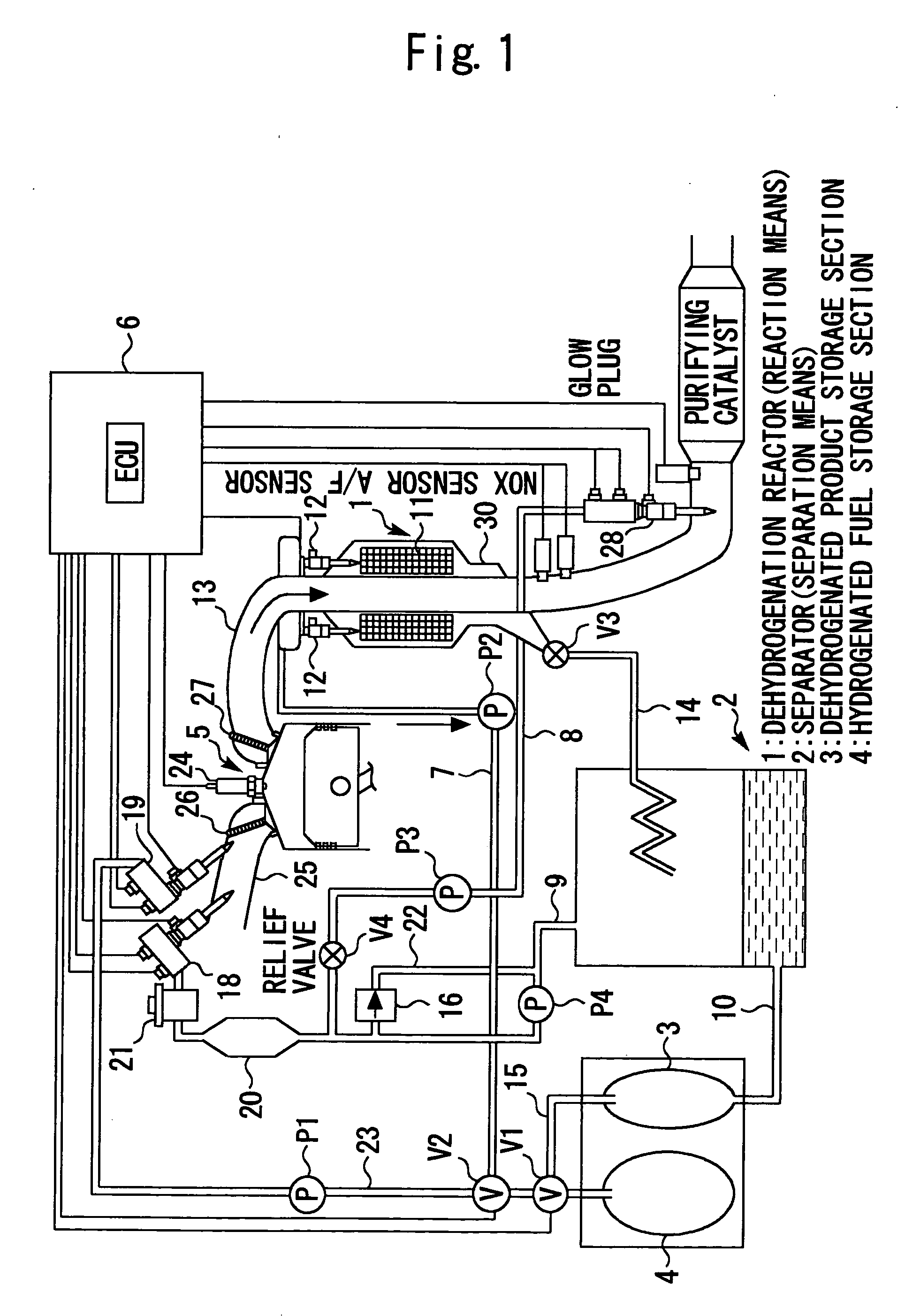
[0029] With a dehydrogenation reactor mounted in an automobile that carries a gasoline-fueled engine, the first embodiment can directly supply hydrogenated gasoline to the engine or let the hydrogenated gasoline react in the presence of a high-temperature catalyst to generate hydrogen-rich gas and dehydrogenated product (gasoline), separate them, make an arbitrary selection, and supply the selection to the engine. The present embodiment can also mix the hydrogen-rich gas, which is derived from dehydrogenation reaction, with exhaust gas, and feed the resulting mixture through a catalyst to purify the exhaust gas.

[0030] The present embodiment is configured as shown in FIG. 1, and will now be described in detail with reference to FIG. 1.

[0031] The hydrogenated gasoline is supplied from the outside to a hydrogenated fuel storage section 4. The hydrogenated fuel storage section 4 is a tank that is shared by a dehydrogenated product storage section 3, which is used aft...

second embodiment

(Second Embodiment)

[Configuration of second embodiment]

[0063] A second embodiment of the present invention will now be described with reference to FIGS. 3 to 5. FIG. 2 illustrates the configuration of a hydrogen-fueled internal combustion engine according to the present embodiment. The system according to the present embodiment includes an internal combustion engine 40. The internal combustion engine 40 communicates with an intake pipe 42 and an exhaust pipe 44.

[0064] The intake pipe 42 incorporates a throttle valve 46 for controlling the intake air amount. A hydrogen supply injector 48 is positioned downstream of the throttle valve 46. An intake port of the internal combustion engine 40 is provided with a gasoline supply injector 50. These injectors 48, 50 have the same configuration and function as the hydrogen supply injector 48 and gasoline supply injector 50 according to the first embodiment, respectively.

[0065] More specifically, the hydrogen supply injector 48 receives the...


PUM

PropertyMeasurementUnit
boiling pointaaaaaaaaaa
temperatureaaaaaaaaaa

Abstract

The present invention relates to a system that is capable of freely selecting one or two or more types of fuel and supplying the selected types of fuel to an internal combustion engine. Disclosed is a hydrogen-fueled internal combustion engine that operates upon receipt of one or more types of fuel that are selected from hydrogenated fuel and a dehydrogenated product and hydrogen, which are obtained by dehydrogenating the hydrogenated fuel. The hydrogen-fueled internal combustion engine comprises: a hydrogenated fuel storage section; reaction means for invoking a dehydrogenation reaction; separation means for separating hydrogen-rich gas and dehydrogenated product; and a dehydrogenated product storage section for storing the separated dehydrogenated product.

Description

TECHNICAL FIELD [0001] The present invention relates to a hydrogen-fueled internal combustion engine, and more particularly to a hydrogen-fueled internal combustion engine that is capable of using hydrogenated fuel or hydrogen-rich gas and dehydrogenated product, which are generated in a vehicle, as fuel. BACKGROUND ART [0002] A gasoline engine, which is gasoline-fueled, has been widely used as a source of power for driving an automobile. A mixture of gasoline, which is main fuel, and air is generally burned to put the gasoline engine into motion. In recent years, however, efforts have been made to commercialize a technology for adding hydrogen to the above air-fuel mixture. [0003] It is also estimated that hydrogen will be increasingly used as automotive fuel not only in gasoline engines, diesel engines, hydrogen engines, and other internal combustion engines, but also in fuel cells for use in an electric automobile and other hydrogen-powered apparatuses other than engines. [0004] ...

Claims


Application Information

Patent Timeline
Patent Type & Authority Applications(United States)
IPC IPC(8): F02B13/00F02M21/02C01B3/26F02M25/00F02M25/10F02M25/12F02M27/02
CPCC01B3/26C01B2203/0277Y02T10/121F02M25/12F02M25/10F02M27/02Y02T10/12F02M21/02F02M25/00
Inventor SHINAGAWA, TOMOHIROATSUMI, TAKASHI
Owner TOYOTA JIDOSHA KK
Why Eureka
Try Eureka