
Array speaker system

a speaker system and array technology, applied in the direction of stereophonic arrangments, transducer casings/cabinets/supports, electrical transducers, etc., can solve the problem of rapid damped high-frequency sound

Active Publication Date: 2007-02-08
YAMAHA CORP
View PDF31 Cites 12 Cited by
  • Summary
  • Abstract
  • Description
  • Claims
  • Application Information

AI Technical Summary

Benefits of technology

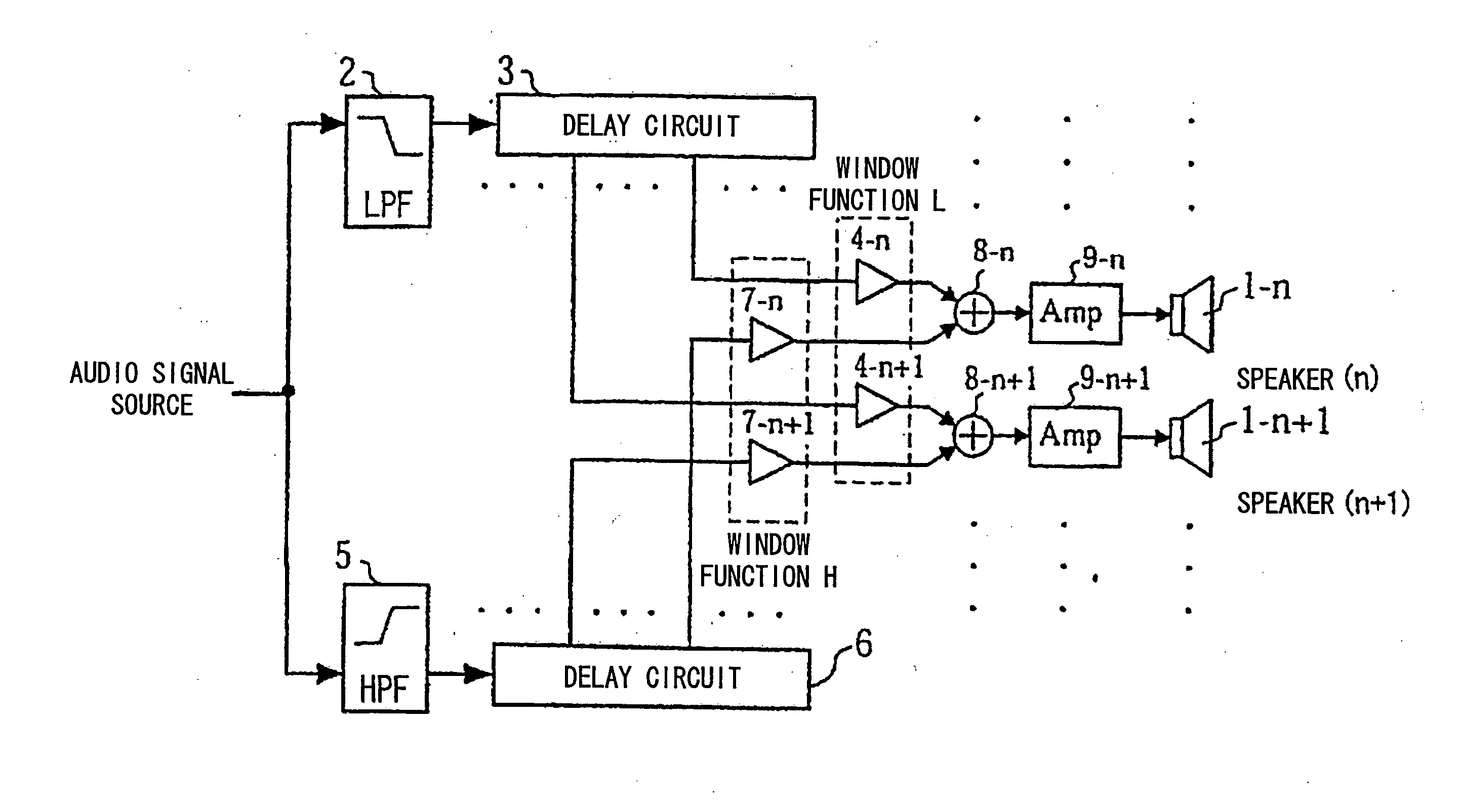
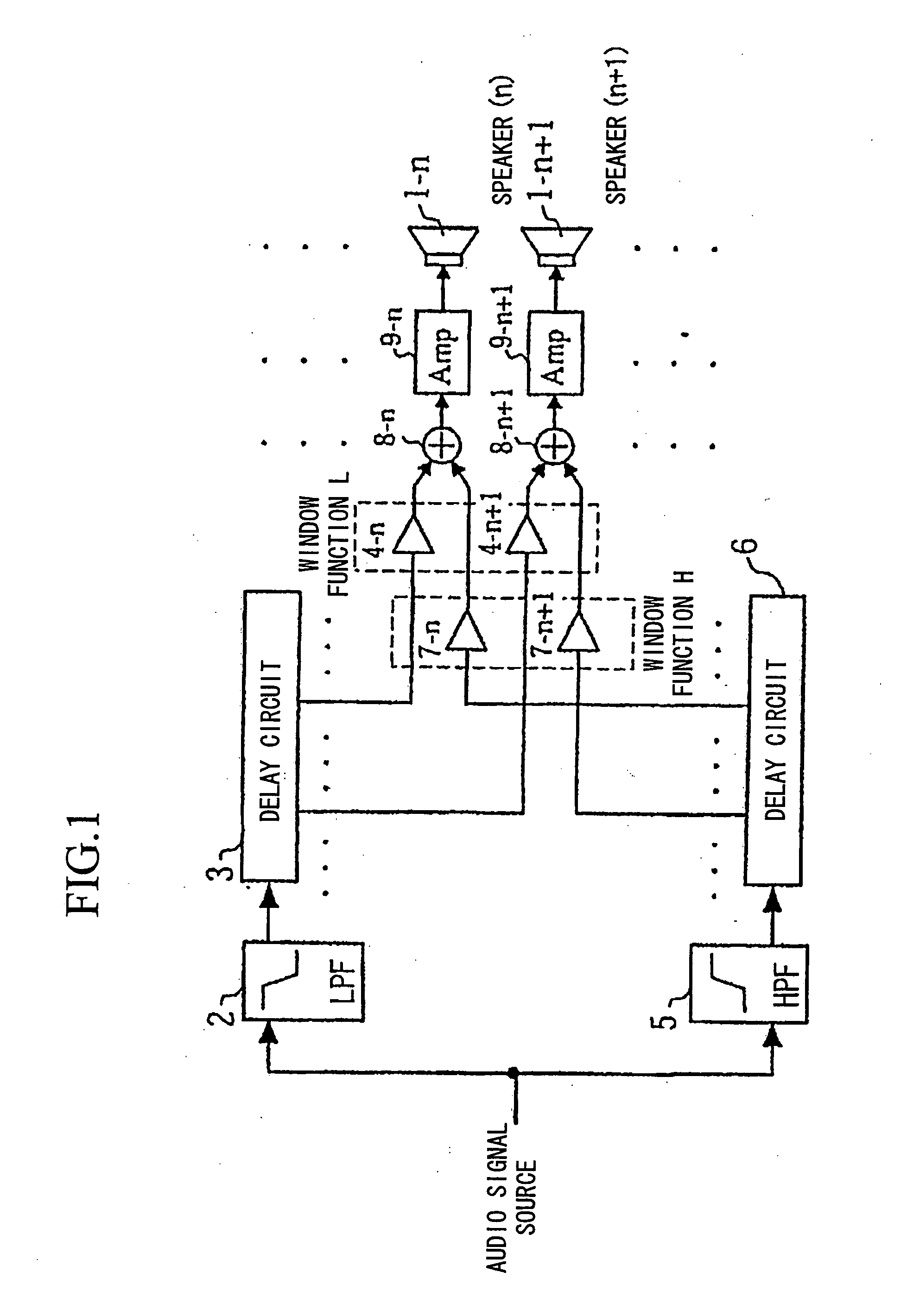
[0014] Furthermore, input audio signals are divided into three frequency bands, i.e., a low-frequency band, an intermediate-frequency band, and a high-frequency band, wherein with respect to the high-frequency band, a relatively large weight is imparted to the center speaker unit in the array speaker, while relatively small weights are imparted to the peripheral speaker units. With respect to the intermediate-frequency band, differences of weights respectively imparted to the center speaker unit and the peripheral speaker units are reduced compared with differences of weights respectively imparted to them with respect to the high-frequency band; alternatively, the same weight is imparted to all of them. With respect to the low-frequency band, no time difference is applied to all the speaker units, so that the same weight is imparted to both the center speaker unit and all of the peripheral speaker units in the array speaker.
[0015] This reduces differences of outlines of sound directivity distributions between high-frequency components and low-frequency components of input audio signals.

Problems solved by technology

At a position distant from the focal point, it is possible to realize hearing of low-frequency sound to some extent; however, hearing of high-frequency sound may be rapidly damped.

Method used


Image

  • Array speaker system
  • Array speaker system
  • Array speaker system

Examples


first embodiment

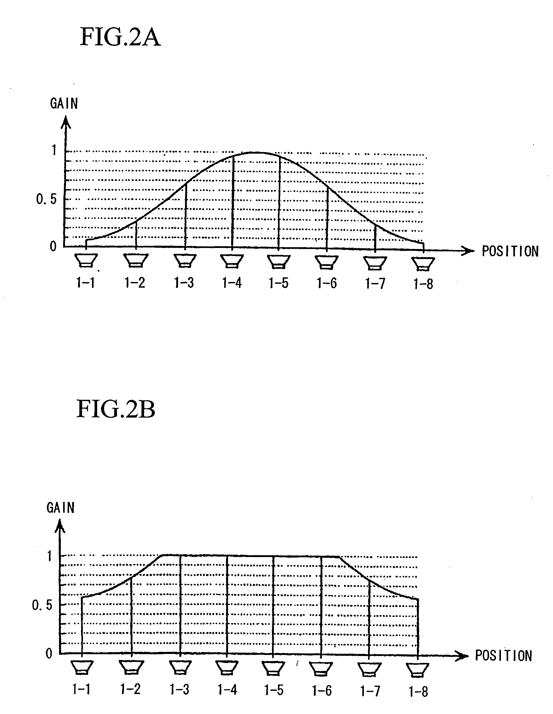
[0052] The first embodiment is designed to use a Hamming window as the window function; of course, it is possible to use other window functions such as a Hanning window.

[0053] Realistically, it is difficult to perform sound directivity control in the low-frequency band whose frequency is several hundreds of hertz or less within the frequency bands of input audio signals due to the relationship between the size of the speaker and the wavelength. For this reason, it is preferable to perform gain adjustment realizing a good balance of sound pressure energy at a sweet spot by not subjecting signal components of the low-frequency band, which are separated from audio signals, to sound directivity control or by subjecting them to non-directivity.

[0054]FIG. 3 is a block diagram showing essential parts of a control circuit of an array speaker system in accordance with a second embodiment of this invention, wherein the low-frequency band whose frequency is several hundreds of hertz or less i...

second embodiment

[0056] As described above, the second embodiment is designed such that low-frequency components of signals whose frequencies are several hundreds of hertz or less and which are extracted by the LPF 12 are not subjected to delay processing for controlling sound directivities (i.e., directivities of audio signal beams) but are simply subjected to gain adjustment and are then supplied to the corresponding speaker units.

[0057] In the aforementioned second embodiment, it is possible to broaden sweet spots with a good balance of sound pressure energy in a wide range of frequencies ranging from low frequencies to high frequencies.

[0058] The aforementioned embodiments are described with respect to a one-dimensional array speaker in which plural speaker units are arrayed in a single line. Similarly, this invention can be applied to a two-dimensional array speaker in which plural speaker units are arrayed in a matrix. In this case, it is divided into one-dimensional arrays in terms of the ro...


PUM


Abstract

Input audio signals are divided into low-frequency components and high-frequency components, both of which are subjected to delay processing in correspondence with desired positions of focal points with respect to speaker units respectively. Delayed low-frequency components are further subjected to weighting using a first window function. Delayed high-frequency components are subjected to weighting using a second window function (e.g., a Hamming window function). Weighted high-frequency components and weighted low-frequency components are added together with respect to the speaker units, which are thus driven respectively. The first window function applied to low-frequency components is made moderate in weighting in comparison with the second window function applied to high-frequency components; thus, it is possible to reduce differences of sound directivities between low-frequency components and high-frequency components of audio signals.

Description

TECHNICAL FIELD [0001] This invention relates to array speaker systems in which plural speaker units are arranged in an array. BACKGROUND ART [0002] Conventionally, technologies for controlling audio signal beams (i.e., sound waves converted into beams having directivities) by use of array speakers, in which plural speaker units are regularly arranged, are known. For example, Japanese Unexamined Patent Application Publication No. H03-159500 and Japanese Unexamined Patent Application Publication No. S63-9300 disclose technologies regarding array speaker systems. [0003] A control method for sound directivity in an array speaker will be described with reference to FIG. 7. [0004] In FIG. 7, reference numerals sp-1 to sp-n designate speaker units that are linearly arranged with prescribed distances therebetween. In the case of generation of an audio signal beam emitted towards a focal point X, a circle Y whose radius matches a distance L from the focal point X is drawn, and delay times (...

Claims


Application Information

Patent Timeline
IPC IPC(8): H04R5/00H04R1/40H04R3/12H04R3/14H04S3/00
CPCH04R3/12H04S3/00H04R2430/20H04R2205/022
Inventor KONAGAI, YUSUKE
Owner YAMAHA CORP
Learn More