Pin-loaded mounting apparatus for a refractory component in a combustion turbine engine

a technology of combustion turbine engine and mounting apparatus, which is applied in the direction of liquid fuel engine, vessel construction, marine propulsion, etc., can solve the problems of ceramic components that cannot be welded to ceramic materials, the thermal changes of shrouds, blades, disks, etc., and the inability of ceramic materials to be welded

Inactive Publication Date: 2007-02-08
SIEMENS ENERGY INC
View PDF23 Cites 70 Cited by
  • Summary
  • Abstract
  • Description
  • Claims
  • Application Information

AI Technical Summary

Problems solved by technology

However, the shroud, blades, disks, and their connections are subject to wide thermal changes during variations in engine operation, including engine shutdowns and restarts.
However, ceramic components are difficult to attach to other components.
Ceramic material cannot be welded, and it is relatively brittle and weak in tension and shear, so it cannot withstand high stress concen

Method used


Image

  • Pin-loaded mounting apparatus for a refractory component in a combustion turbine engine
  • Pin-loaded mounting apparatus for a refractory component in a combustion turbine engine
  • Pin-loaded mounting apparatus for a refractory component in a combustion turbine engine

Examples


Embodiment Construction

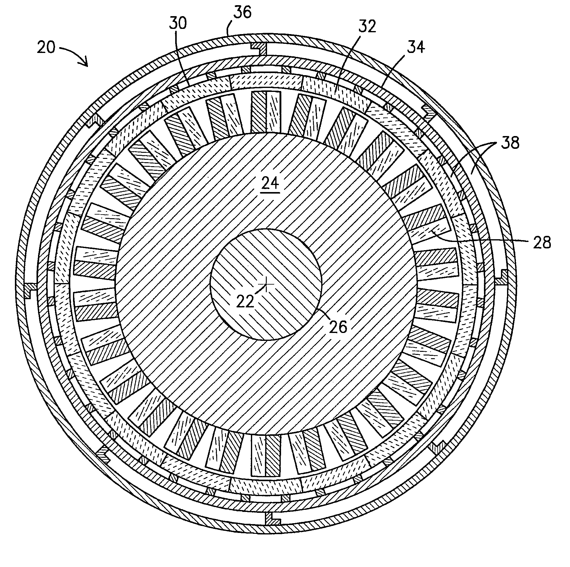
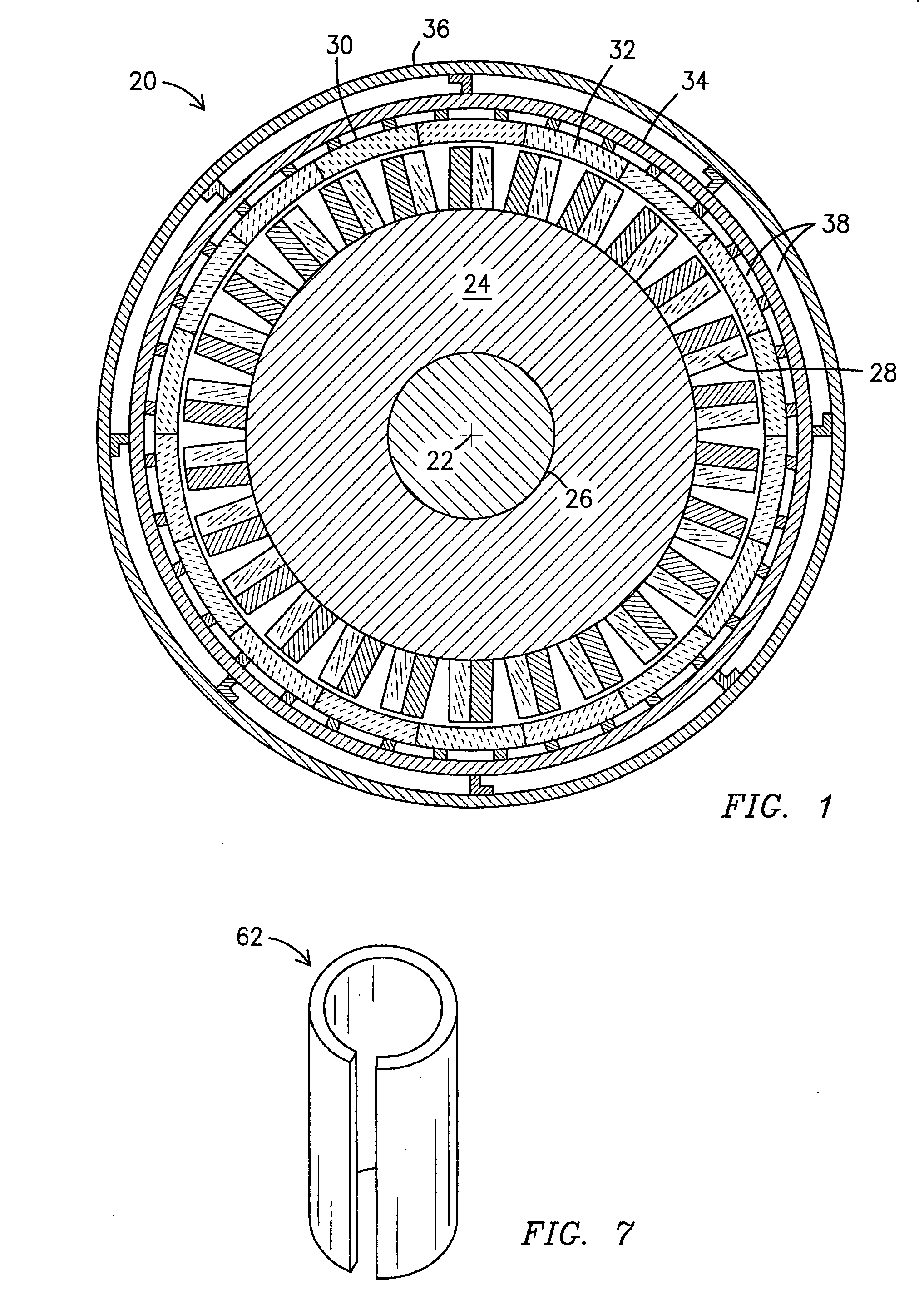
[0014]FIG. 1 shows a schematic sectional view of a combustion turbine engine 20 taken on a plane normal to the engine shaft axis 22 through a disk 24 mounted on the shaft 26 with turbine blades 28 and an associated shroud ring 30 and a support structure. The shroud ring 30 is assembled in arcuate segments 32. The support structure for a shroud ring 30 may comprise an intermediate support ring 34 between the shroud ring 30 and the engine casing 36. The support ring 34 is attached to the engine casing 36, and the segments 32 of the shroud ring are attached to the support ring 34. The support ring 34 and the engine casing 36 may be made of metal, although this is not a requirement of the invention. Cooling air 38 flows between the shroud 34 and engine casing 36 under enough pressure to prevent combustion gases from entering this area through clearances between shroud segments 32. Cooling air may also flow in channels within the blades (not shown). In the following description “axial” m...


PUM

PropertyMeasurementUnit
Electrical conductanceaaaaaaaaaa
Refractoryaaaaaaaaaa

Abstract

An apparatus for mounting a refractory component such as a turbine shroud ring segment (32) with a ceramic core (42) onto a combustion turbine engine structure (34). The ring segment has a ceramic matrix composite skin (40), and optionally, a thermal insulation layer (46). A pin (60) is inserted through a bore (48) in the core and through an attachment bar (54) with ends received in wells (50) in the core. The attachment bar may be attached to a backing member, or tophat (64), by a biasing device (76) that urges the refractory component snugly against the backing member to eliminate vibration. The backing member and refractory component have mating surfaces that may include angled sides (52S, 70). The backing member is attached to the engine structure. Turbine shroud ring segments can be attached by this apparatus to a surrounding structure to form a shroud ring.

Description

FIELD OF THE INVENTION [0001] This invention relates generally to the field of combustion turbine engines, and more particularly to the use of ceramics and ceramic matrix composite materials in a combustion turbine engine. BACKGROUND OF THE INVENTION [0002] A combustion turbine engine has a rotating shaft with several circular arrays of radially oriented aerodynamic blades mounted around the circumferences of disks on the shaft. Closely surrounding these blades is a refractory shroud that contains the flow of hot combustion gasses passing through the engine. This shroud must withstand temperatures of over 1400° C. reliably over a long life span. Close spatial tolerances must be maintained in the gap between the blade tips and the shroud for engine efficiency. However, the shroud, blades, disks, and their connections are subject to wide thermal changes during variations in engine operation, including engine shutdowns and restarts. The shroud must insulate the engine case from combust...

Claims


Application Information

Patent Timeline
IPC IPC(8): B63H1/16
CPCF01D9/04F05D2300/21F05D2240/11
Inventor CAMPBELL, CHRISTIAN X.KELLER, DOUGLAS A.GONZALEZ, MALBERTO F.
Owner SIEMENS ENERGY INC
Why Eureka
Try Eureka