High Temperature Wellbore Monitoring Method and Apparatus

Inactive Publication Date: 2007-02-08
SCHLUMBERGER TECH CORP
View PDF32 Cites 12 Cited by
  • Summary
  • Abstract
  • Description
  • Claims
  • Application Information

AI Technical Summary

Benefits of technology

[0007] The master element can further comprises a controlled current source supplying a current to the downhole element via the sealed connection and the current being alternatively switched in polarity. The surface electronics sends a controlled current to each respective sensor and receives the voltage across each sensor individually. By this means the effects of the cable's resistance upon the measurement is minimized. Electromagnetic interference, noise pickup and other disturbances, such as thermoelectric

Problems solved by technology

Unfortunately, the wire sags with time which results in the measurement drifting out of calibration quickly, depending on the temperature.
This device is also affected by temperature excursions due to inelastic effects of the wire's and diaphragm's metallurgy and bonding materials.
This is prone to stress corrosion failure and leaks caused b

Method used


Image

  • High Temperature Wellbore Monitoring Method and Apparatus
  • High Temperature Wellbore Monitoring Method and Apparatus
  • High Temperature Wellbore Monitoring Method and Apparatus

Examples


Example

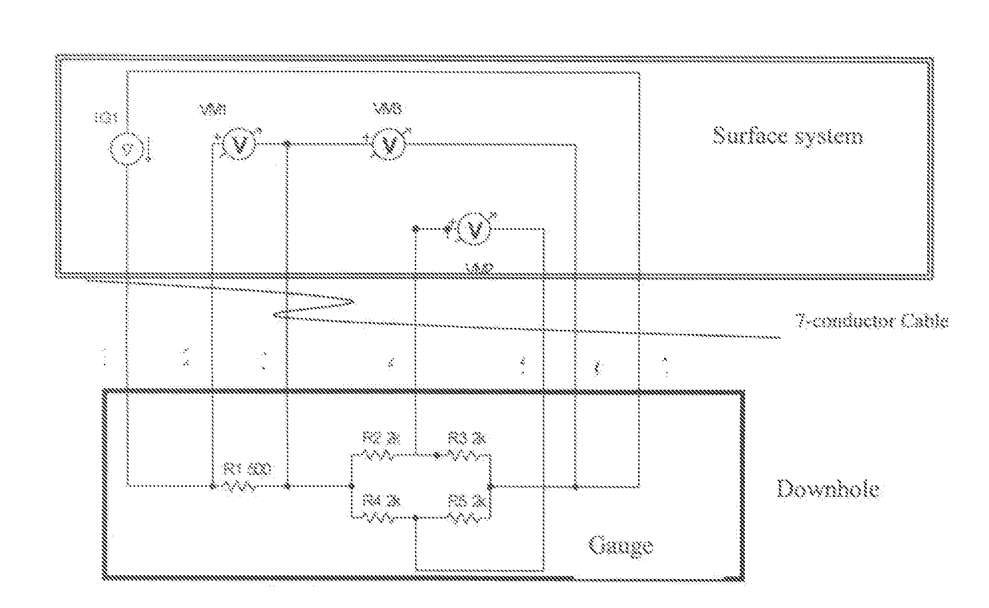
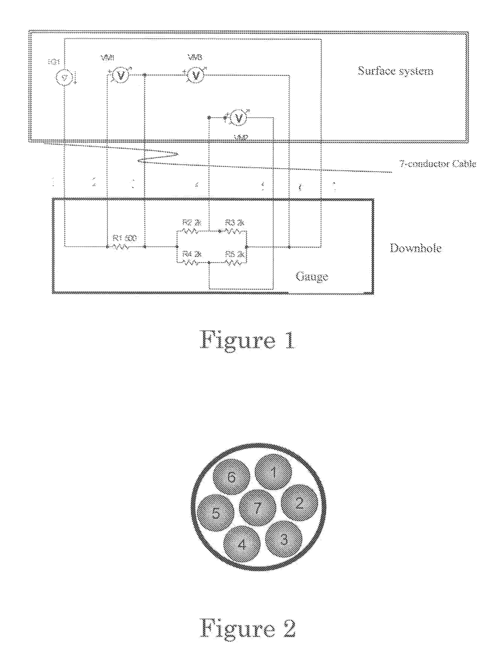
[0013] A permanent pressure gauge system is directed to monitor the extreme downhole environmental conditions within steam injection wells or geothermal wells where operating temperatures can range up to 250° C. Compared to typical downhole reservoir monitoring systems, the absolute pressure in these applications is relatively low and the metrological requirements are modest for pressure and temperature measurement accuracy, resolution, and stability. According to a preferred embodiment of the invention, the application is focused on monitoring steam injection operations for enhanced recovery of heavy, i.e. viscous, oil, specifically for Steam Assisted Gravity Drainage (SAGD) applications. The economic drivers demand that the equipment for these applications must be very low cost, yet robust, simple to operate and reliable.

[0014] Also, typical conditions in the steam injection well environment are: [0015] Well length / depth: up to 1000 m (currently 200 to 400 m), [0016] Maximum Temp...


PUM


Abstract

The invention provides an apparatus for use in high temperature conditions, constituted of a downhole element and a master element connected together via a sealed connection; wherein the downhole element comprises a temperature sensor and a pressure sensor without any electronics and is embedded in a sealed housing resistant to high temperature; wherein the master element comprises electronics needed for function of the temperature sensor and the pressure sensor; and wherein the sealed connection is resistant to high temperature.

Description

FIELD OF THE INVENTION [0001] The present invention relates to an apparatus and associated method for monitoring pressure and / or temperature in severe environments as for example high temperature. DESCRIPTION OF THE PRIOR ART [0002] For the moment, for high temperature application, pressure measurements are done with a vibrating wire sensor system. Basically, the vibrating sensor wire is in tension, with at least one end attached to a pressure diaphragm. The wire is driven into oscillation via an electromagnet coil. An electromagnet picks up the wire's vibration frequency that is related, in a precisely known way, to the applied pressure on the diaphragm. The electromagnetic driver and pickup are connected to surface via wires in a four-conductor cable. Interrogation electronics at the surface drive, and measure the vibrating or resonant frequency. Unfortunately, the wire sags with time which results in the measurement drifting out of calibration quickly, depending on the temperatur...

Claims


Application Information

Patent Timeline
IPC IPC(8): G01V1/28E21B47/017E21B47/06
CPCG01K1/12E21B47/06
Inventor POPILIAN, CONSTANTINCADERE, DIMITRIWIESE, JACQUESOSTIZ, JEAN-CLAUDEVENERUSO, ANTHONY
Owner SCHLUMBERGER TECH CORP
Why Eureka
Try Eureka