
Ion extraction devices, mass spectrometer devices, and methods of selectively extracting ions and performing mass spectrometry

a mass spectrometer and ion extraction technology, applied in the field of analytical devices, can solve the problems of loss of sensitivity, difficult to exploit the behaviour of scanning mass spectrometers, and difficult to predict the deterministic analysis of separation

Active Publication Date: 2007-02-15
MICROMASS UK LTD
View PDF3 Cites 49 Cited by
  • Summary
  • Abstract
  • Description
  • Claims
  • Application Information

AI Technical Summary

Benefits of technology

[0009] generating further potentials to provide an effective potential which prevents ions from being extracted from an extraction region;
[0135] in which the ejection of the ions from the ion trap and the scanning of the mass scanning mass spectrometer are synchronised so that the mass of at least some of the ions directed into the mass scanning mass spectrometer thereby enhancing the sensitivity of the mass scanning mass spectrometer.

Problems solved by technology

A major drawback of any scanning mass spectrometer is a loss of sensitivity due to poor duty cycle.
The behaviour of such devices depends on the ion density present within the guide and as such it is difficult to exploit this behaviour as a predictable deterministic analytical separation.
These RF devices are able to trap in three dimensions in a way which is impossible to achieve using purely electrostatic ion optical elements.
This is because Laplace's equation, which describes the behaviour of electrostatic fields, contains no true potential minima but only saddle points which on their own are insufficient to give true three dimensional trapping.
This sluggish motion of ions in the guides has led to problems when interfacing with fast scanning devices such as analytical quadrupoles.

Method used


Image

  • Ion extraction devices, mass spectrometer devices, and methods of selectively extracting ions and performing mass spectrometry
  • Ion extraction devices, mass spectrometer devices, and methods of selectively extracting ions and performing mass spectrometry
  • Ion extraction devices, mass spectrometer devices, and methods of selectively extracting ions and performing mass spectrometry

Examples


Embodiment Construction

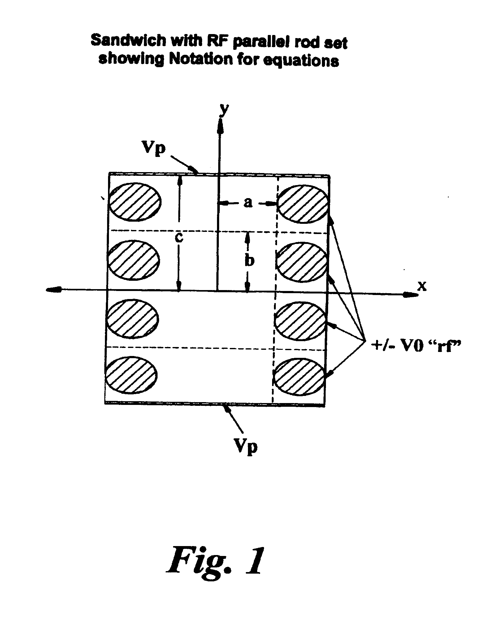
[0183] The general form of the effective potential (both from rf and electrostatic source) is derived using the adiabatic approximation [Gerlich, ibid] and is given by Veff⁡(Ro)⁢:=q2·Eo24·M·Ω2+q·Φ[equation⁢ ⁢1]

where R0 is the slowly varying position of an ion, q is its charge, E0 is the magnitude of the oscillatory electric field of angular frequency Ω at position R0 and M is its mass. The equation also includes the classical electrostatic potential qøs where øs is a voltage created by DC potentials applied to electrodes in any general system. It can be seen that the potential due to the oscillatory field is proportional to charge squared while the electrostatic potential is proportional to charge. The present invention exploits this relationship to separate ions of similar mass but differing charge.

[0184] The form of the effective potential from an oscillatory field in quadrupoles, hexapoles, octopoles etc has been calculated by Gerlich and is of the form: V⁡(r)⁢:⁢=n2·q2·Vo24·M...


PUM


Abstract

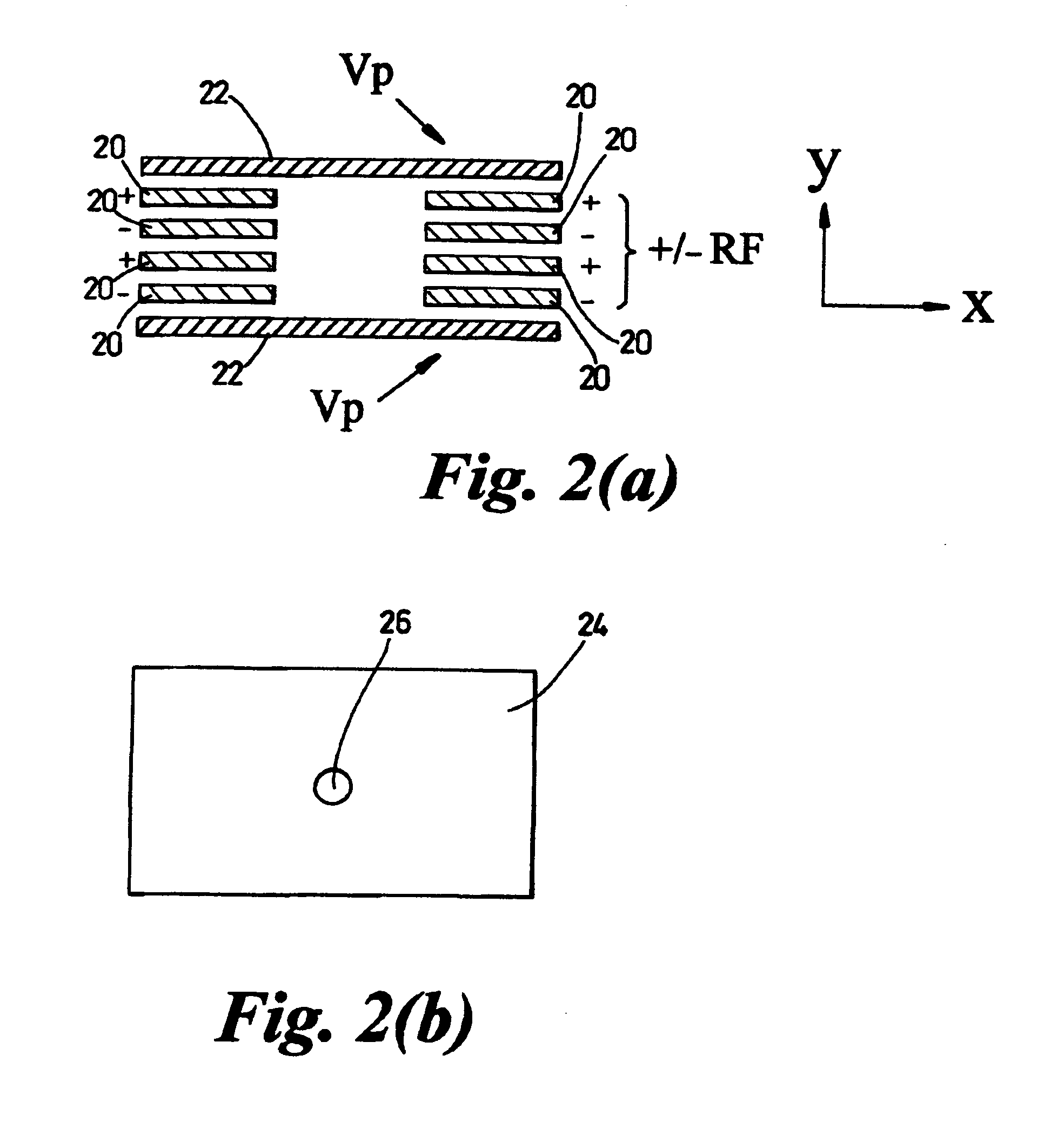
There is disclosed a method of selectively extracting ions comprising the steps of: providing a supply of ions in a body of gas; generating a ponderomotive ion trapping potential generally along an axis; generating further potentials to provide an effective potential which prevents ions from being extracted from an extraction region; trapping ions in said effective potential; and selectively extracting ions of a predetermined m / z ratio or ion mobility from the extraction region; in which the characteristics of the effective potential which prevent ions from being extracted from the extraction region are caused, at least in part, by the generation of the ponderomotive ion trapping potential.

Description

FIELD OF THE INVENTION [0001] This invention relates to ion extraction devices, analytical devices incorporating same, methods of extracting ions and methods of analysing ions or physical phenomena associated with ions, with particular, but by no means exclusive, reference to mass spectrometry and to selective extraction of ions of different mass (m) to charge (z) ratios (henceforth termed “m / z” ratios) and / or of different ion mobilities. BACKGROUND OF THE INVENTION [0002] Mass scanning mass spectrometers, such as quadrupole mass spectrometers, are ubiquitous analytical devices. A major drawback of any scanning mass spectrometer is a loss of sensitivity due to poor duty cycle. For example, if a quadrupole mass spectrometer scans a mass range of x Da with a mass resolution or peak width of y Da, then a duty cycle of y / x is obtained. For a conventional quadrupole mass spectrometer, realistic values of x and y are 1000 and 1 respectively, resulting in a duty cycle of only 1 / 1000 or 0.1...

Claims


Application Information

Patent Timeline
Patent Type & Authority Applications(United States)
IPC IPC(8): H01J3/14
CPCH01J49/427
Inventor HOYES, JOHN BRIAN
Owner MICROMASS UK LTD
Learn More