Eureka AIR delivers breakthrough ideas for toughest innovation challenges, trusted by R&D personnel around the world.

Light scan device and image display device

Inactive Publication Date: 2007-02-15
SEIKO EPSON CORP
View PDF4 Cites 8 Cited by
  • Summary
  • Abstract
  • Description
  • Claims
  • Application Information

AI Technical Summary

Benefits of technology

[0006] An advantage of some aspects of the invention is to provide a light scan device for displaying a bright image with high quality and an image display device incorporating the light scan device.
[0007] To solve the problems and achieve the advantage, the invention can provide a light scan device which forces a beam light depending on an image signal to scan, including: a light source part for supplying the beam light; and a scanning part for forcing the beam light from the light source part to scan an illumination-target region in a first direction and a second direction substantially orthogonal to the first direction, wherein the scanning part is driven so that a frequency with which the beam light is forced to scan in the first direction is higher than a frequency with which the beam light is forced to scan in the second direction, and a spot formed on the illumination-target region by the beam light has a form with a shorter size in the first direction than in the second direction.
[0008] Formation of a spot having a form, whose size in the first direction is shorter than the size in the second direction, can reduce the blurring caused when the beam light for display of a pixel enters the region of another pixel. Also, the lighting time of the beam light with respect to a pixel can be elongated by making the width of the spot in the first direction smaller. Reduction in blurring caused when a beam light for display of a pixel enters the region of another pixel allows an image to be displayed with a high resolution. In addition, a bright image can be displayed by elongating the lighting time of a beam light with respect to a pixel. Further, formation of a spot having a form, whose size is longer in the second direction than in the other direction, can narrow a gap between pixels in the second direction. Still further, when the gap between scanning lines along which the beam light is forced to scan is made inconspicuous, a seamless image can be displayed. Thus, a light scan device for displaying a bright and high-quality image can be obtained.

Problems solved by technology

Then, the occurrence of an event such that an image is blurred by modulated light incident on a location different from a location specified by the address information that an image signal carries, i.e. so-called crosstalk, makes it difficult to display an image with a high resolution owing to the unclear outline of the image, etc.
However, in the case where the spot has a circular form with a size comparable to that of the pixel, the lighting time of the laser light for display by the pixel is shortened considerably, which leads to a dark image.
However, in this case, the gap between scanning lines along which the laser light is made to scan becomes more conspicuous, which makes it difficult to offer a seamless image.
As described above, in the art there has been a problem such that it is difficult to display a bright image with high quality.

Method used


Image

  • Light scan device and image display device
  • Light scan device and image display device
  • Light scan device and image display device

Examples


first embodiment

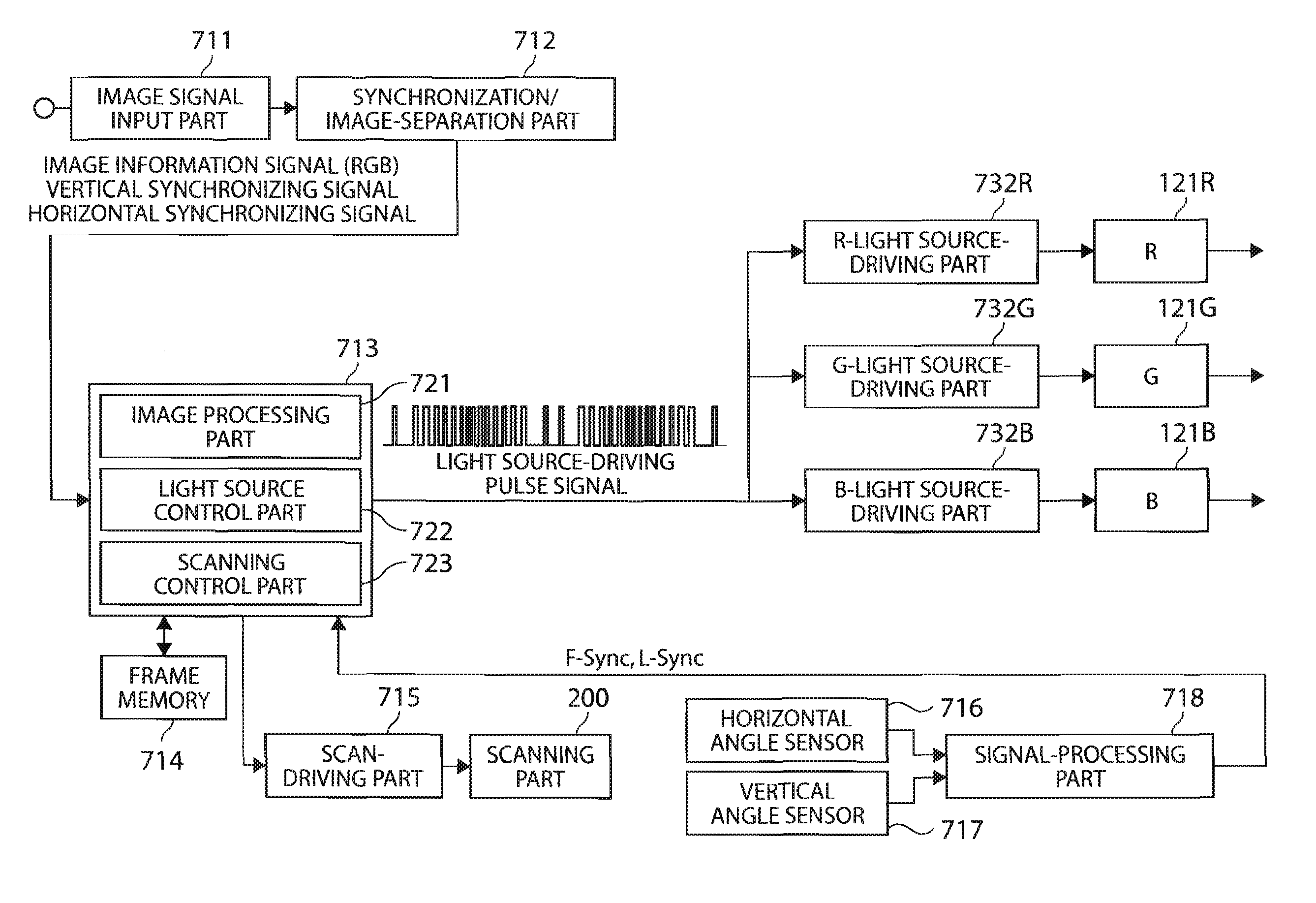
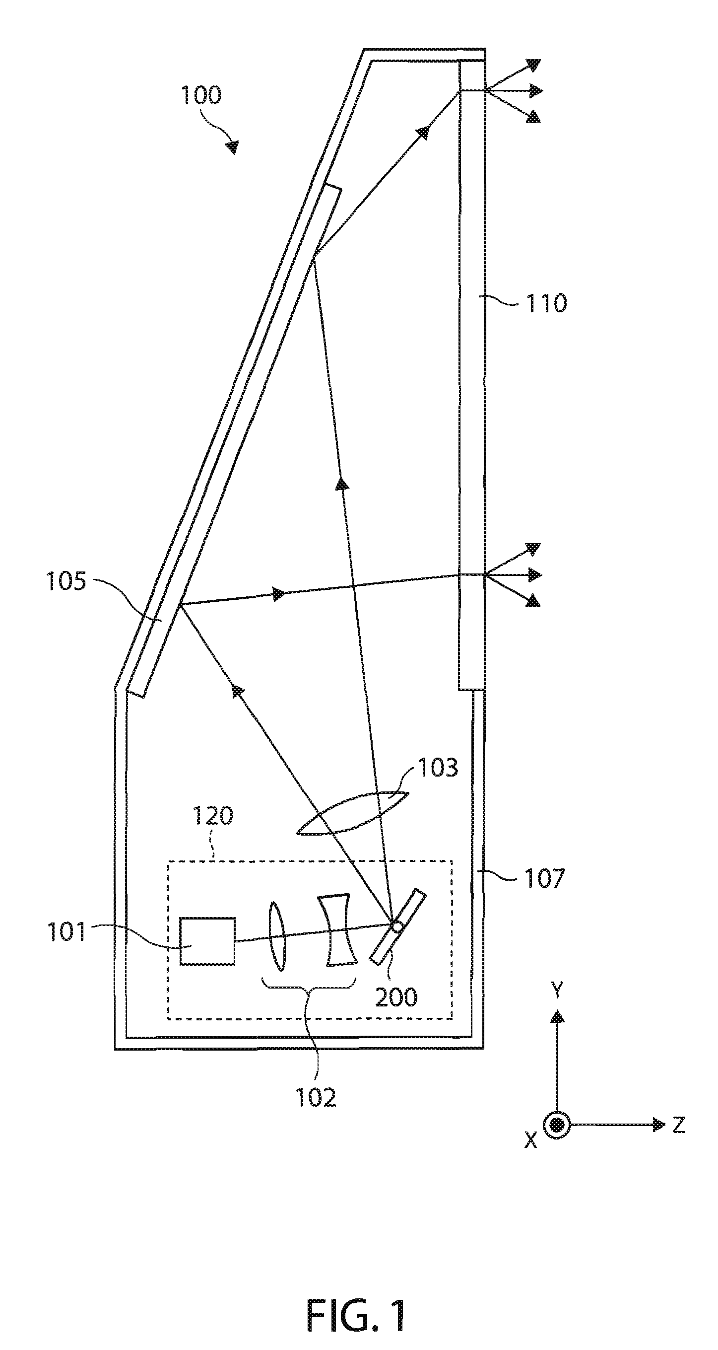
[0041]FIG. 1 shows a schematic configuration of an image display device 100 in association with the first embodiment of the invention. The image display device 100 is a so-called rear projector such that a laser light is supplied to one plane of a screen 110 and an image is watched and / or enjoyed by observing light emitted from the other plane of the screen 110. A light scan device 120 provided in the image display device 100 forces the laser light depending on an image signal to scan. The light scan device 120 has a laser device 101, an illumination system 102, and a scanning part 200. The image display device 100 uses laser light from the light scan device 120 to display an image.

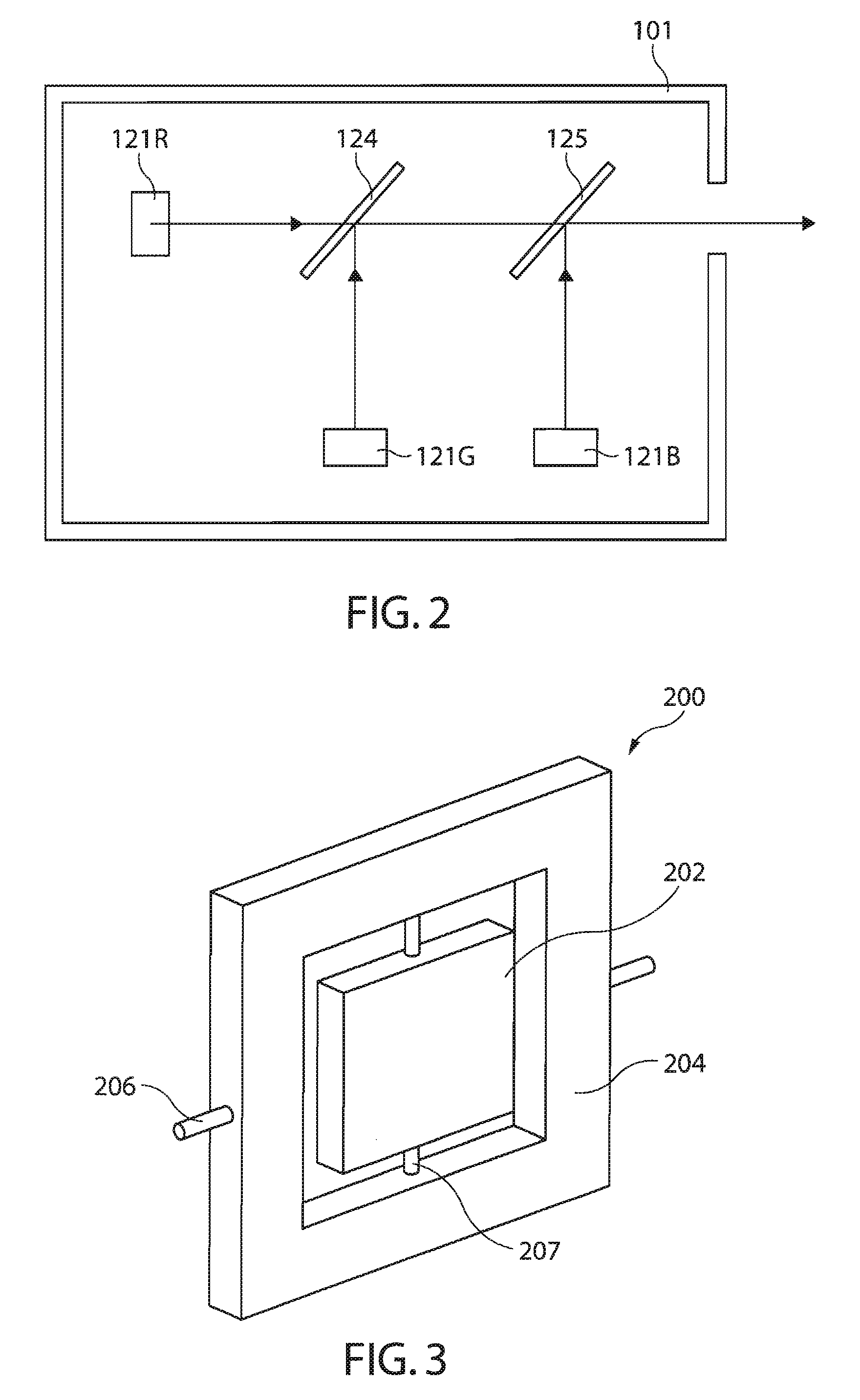
[0042]FIG. 2 shows a schematic configuration of the laser device 101. The laser device 101 has an R-light source 121R for supplying a red laser light (hereinafter referred to as “R light”) as a beam light; a G-light source part 121G for supplying a green laser light (hereinafter referred to as “G light”)...

second embodiment

[0079]FIG. 13 is a view of assistance in explaining an image display device in association with the second embodiment of the invention, and it shows a spot SP2 of laser light in an illumination-target region. In the first embodiment the lighting time t of the laser light is determined based on the form of a spot SP1, whereas in the second embodiment the form of a spot SP2 is determined from the time t during which the laser light is kept in ON state. Also, in this embodiment, the spot SP2 has a substantially rectangular form having a width dy in Y direction, i.e. the second direction, and a width dx in X direction, i.e. the first direction, in which the width dx is shorter than the width dy. Here, the same parts as those in the first embodiment are identified by the same reference characters to omit their repeated descriptions.

[0080] Here, when the interval between the center position O of the spot SP2 at the timing when the laser light is turned on and the center position O′ of th...

third embodiment

[0084]FIG. 14 shows a schematic configuration of an image display device 1700 in association with the third embodiment of the invention. The image display device 1700 is a so-called front projection type projector by which a laser light is supplied to a screen 1705 provided on the side of an observer and an image can be watched and / or enjoyed by observing the light reflected by the screen 1705. The image display device 1700 has a light scan device 120 as in the first embodiment. Here, the same parts as those in the first embodiment are identified by the same reference characters to omit their repeated descriptions. Laser light from the light scan device 120 passes through the projection optical system 103 and then impinges on the screen 1705. Also, in this embodiment, a bright and high-quality image can be displayed.

[0085] In this embodiment, the light source parts for individual color lights are arranged so as to supply respective laser lights. However, they are not so limited to ...


PUM


Abstract

A light scan device which forces a beam light depending on an image signal to scan, including: a light source part for supplying the beam light; and a scanning part for forcing the beam light from the light source part to scan an illumination-target region in a first direction and a second direction substantially orthogonal to the first direction, wherein the scanning part is driven so that a frequency with which the beam light is forced to scan in the first direction is higher than a frequency with which the beam light is forced to scan in the second direction, and a spot formed on the illumination-target region by the beam light has a form with a shorter size in the first direction than in the second direction.

Description

BACKGROUND [0001] 1. Technical Field [0002] The present invention relates to a light scan device and an image display device. Particularly, it relates to a technique for a light scan device for causing a laser light modulated according to an image signal to scan thereby to display an image. [0003] 2. Related Art [0004] In recent years, a laser projector by which an image is displayed by forcing a laser light to scan has been proposed as an image display device for displaying an image. Laser light is characterized by its high monochromaticity and directivity. Therefore, a laser projector has an advantage such that an image can be obtained with a good color reproducibility. A technique for an image display device to display an image by forcing a laser light to scan has been proposed by e.g. JP-A-1-245780. [0005] Typically, a laser light is shaped so that the form of a spot formed in an illumination-target region of a screen or the like is substantially circular. In this case, performi...

Claims


Application Information

Patent Timeline
IPC IPC(8): G09G3/36
CPCH04N9/3129G09G3/02
Inventor YAMAZAKI, TETSUROTAKEDA, TAKASHIUCHIKAWA, DAISUKEMIYAZAWA, YASUNAGA
Owner SEIKO EPSON CORP
Why Eureka
Eureka Blog
Learn More