Directed attention digital video recordation

a digital video and image technology, applied in the field of captured images and recorded images, can solve the problems of not being able to use images for positive recognition, recording the path of objects, and all existing recording systems have the same limitation of the number of pixels on the target required for forensic recognition, so as to reduce the content of archived data and reduce the effect of pixel conten

Active Publication Date: 2007-02-15
CHECKVIDEO
View PDF47 Cites 61 Cited by
  • Summary
  • Abstract
  • Description
  • Claims
  • Application Information

AI Technical Summary

Benefits of technology

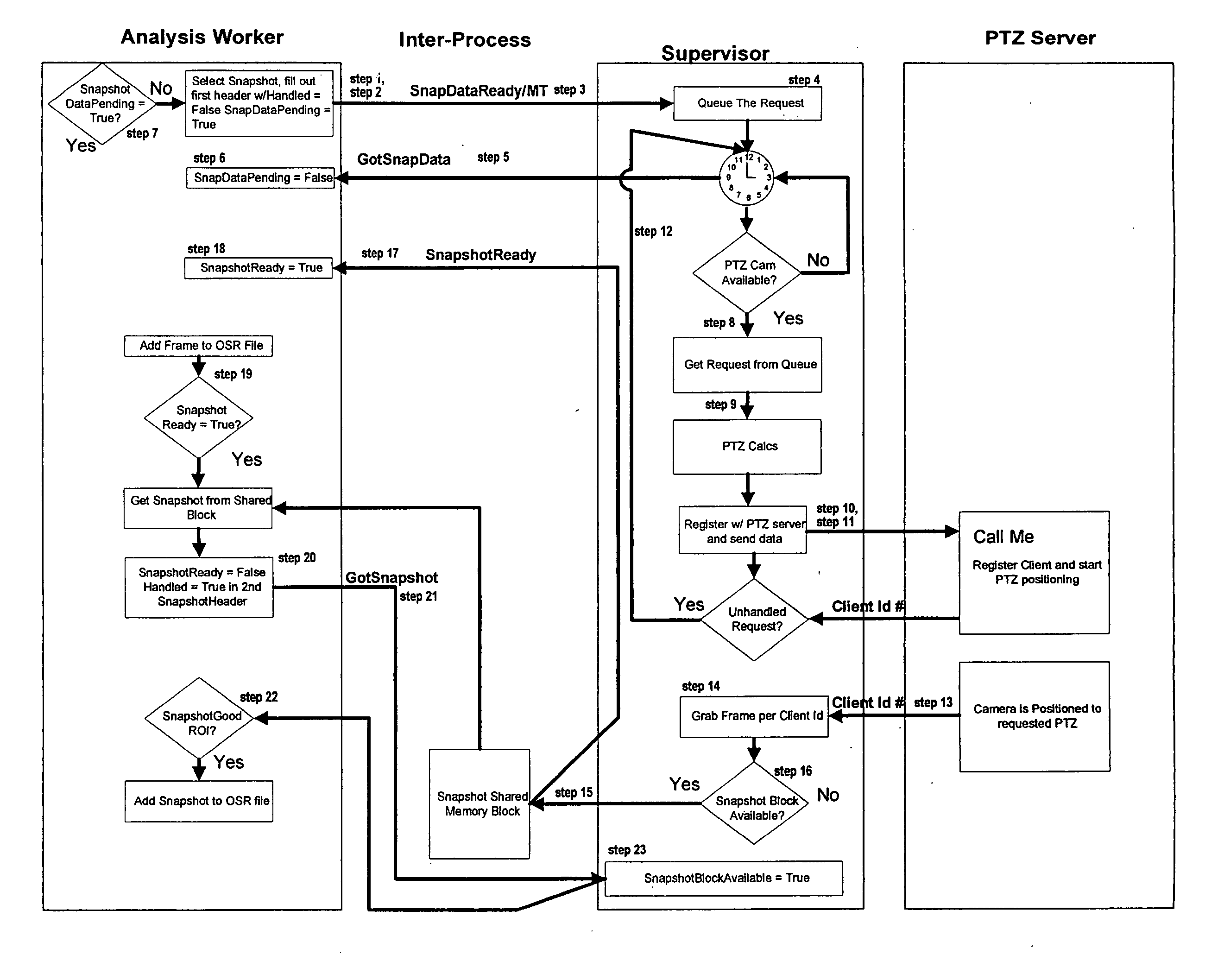
[0052] After thus capturing a snapshot of the area of interest by operation of the PTZ camera, the method provides storage (and ultimately archiving) of the scene image in a file format that includes the snapshot, as well as the metadata. The captured image (snapshot) has substantially much less pixel content than the overall view so that the archived data is greatly minimized.

Problems solved by technology

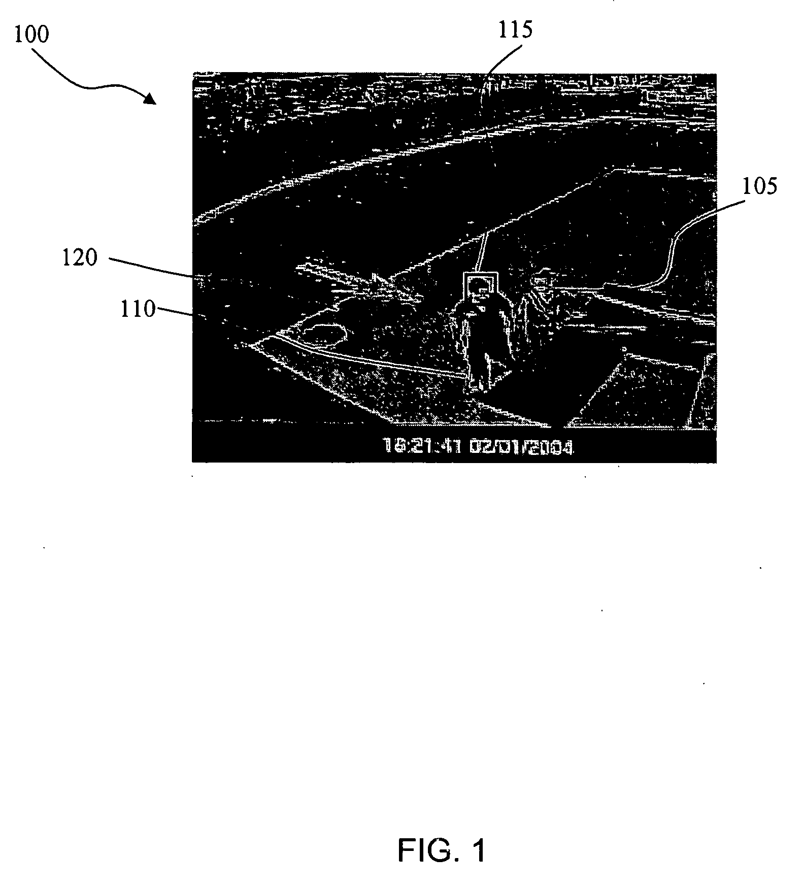
However, with so few pixels on the target we can only record the path of the object.
All existing recording systems have the same limitation of the number of pixels on the target required for forensic recognition.
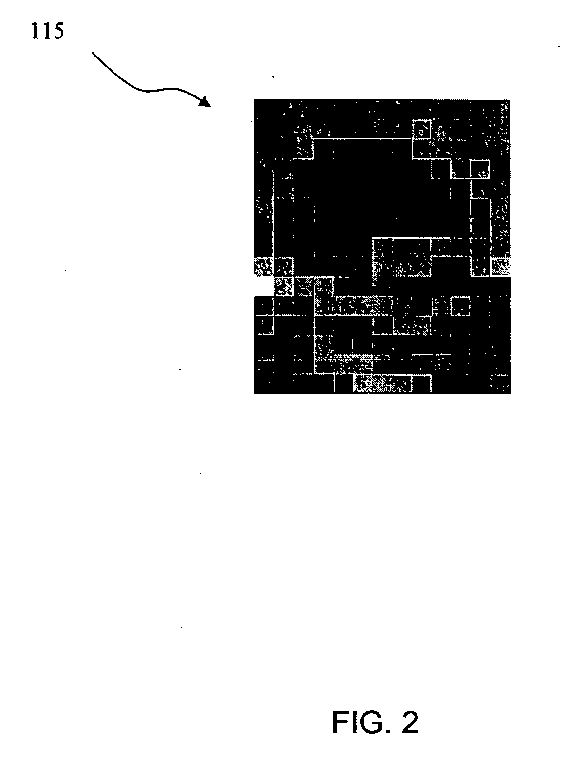
The victim's abduction took place so close to the camera that the abductor's face occupied one half of one percent of the scene, and even so, the image could not be used for positive recognition.
It is simply not possible to have enough 640×480 cameras monitoring any real scene to obtain an image of the forensic value as FIG. 3.
Yet, even a HDTV resolution camera cannot get enough pixels, for forensic purposes, of a person beyond the near field of FIG. 1.
Clearly, a brute force higher resolution sensor will overwhelm current storage devices.
Digital Video Recorders (DVRs) currently in use have no “knowledge” of the content of the video that is being recording.
Yet, none combines the recording of a video camera with images from an automatically controlled PTZ camera and links the location of the acquired images with a fixed camera view.

Method used


Image

  • Directed attention digital video recordation
  • Directed attention digital video recordation
  • Directed attention digital video recordation

Examples


Embodiment Construction

[0074] This specification discloses one or more embodiments that incorporate the features of this invention. The disclosed embodiment(s) merely exemplify the invention. The scope of the invention is not limited to the disclosed embodiment(s). The invention is defined by the claims appended hereto.

[0075] The embodiment(s) described, and references in the specification to “one embodiment”, “an embodiment”, “an example embodiment”, etc., indicate that the embodiment(s) described may include a particular feature, structure, or characteristic, but every embodiment may not necessarily include the particular feature, structure, or characteristic. Moreover, such phrases are not necessarily referring to the same embodiment. Further, when a particular feature, structure, or characteristic is described in connection with an embodiment, it is understood that it is within the knowledge of one skilled in the art to effect such feature, structure, or characteristic in connection with other embodi...


PUM


Abstract

The present invention describes systems and methods of incorporating detailed snapshots of targeted areas of interest into a video or digitized recording of the overall scene including metadata to link the snapshots to the time and location in the overall scene from which the snapshot was acquired. A single fixed high-resolution scene camera or a fixed standard resolution scene camera of analog or IP connected type is used, co-located with at least one pan-tilt-zoom (PTZ) camera or by using the same scene camera in a mode where less than full resolution of the scene camera is used for video but snapshots of areas are captured by the same camera where higher resolution thereof is used for snapshots than for video. The area of interest is selected by the object-tracking feature of an intelligent video system, operated without human intervention, by electronically-implemented identification of the existence of area-specific subjects or targets of interest in the scene image field.

Description

CROSS-REFERENCE TO RELATED APPLICATIONS [0001] The present application claims the benefit of U.S. Provisional Patent Application No. 60 / 701,804, filed on Jul. 22, 2005, entitled, “Directed Attention Digital Video Recordation with Software Scope” by Garoutte et al., which is incorporated herein by reference in its entirety. [0002] The following patent applications of common assignee are herein incorporated by reference in their entirety: [0003]“System for Automated Screening of Security Cameras”, U.S. patent application Ser. No. 09 / 773,475, filed Feb. 1, 2001, which resulted in granted U.S. Pat. No. 6,940,998 B2, issued on Sep. 6, 2005. [0004]“Object Selective Video Recording”, U.S. patent application Ser. No. 10 / 041,402, filed Jan. 8, 2002.BACKGROUND OF THE INVENTION [0005] 1. Field of the Invention [0006] The invention relates to capture and recording of images for analysis, storage and other purposes, and more particularly to directed image video capture and digital video recordat...

Claims


Application Information

Patent Timeline
Patent Type & Authority Applications(United States)
IPC IPC(8): H04N7/18H04N5/225
CPCG08B13/19608G08B13/19643G08B13/19671G08B13/19693H04N5/232H04N7/181H04N5/23219H04N5/23232H04N5/76H04N5/765H04N5/77H04N5/23206H04N23/661H04N23/61H04N23/611H04N23/951
Inventor GAROUTTE, MAURICE V.WANG, FENGTANGFITZGERALD, MICHAEL T.
Owner CHECKVIDEO
Why Eureka
Try Eureka