Line narrowing module, light source of exposure apparatus comprising the same, and method of producing exposure light using line narrowing

a line narrowing and light source technology, applied in the field of exposure apparatuses, can solve the problems of chromatic aberration that is difficult to correct using additional optics, waste of optical energy, and large bandwidth, and achieves the effect of high optical energy efficiency

Active Publication Date: 2007-02-15
SAMSUNG ELECTRONICS CO LTD
View PDF6 Cites 5 Cited by
  • Summary
  • Abstract
  • Description
  • Claims
  • Application Information

AI Technical Summary

Benefits of technology

[0011] An object of the present invention is to provide a light source of an exposure apparatus that is highly optically energy efficient at producing exposure light having a narrow bandwidth.
[0012] Similarly, another object of the present invention is to provide a highly optically energy efficient method of producing exposure light having a narrow bandwidth.
[0013] Another object of the present invention is to provide a light source of an exposure apparatus that will consistently output with precision a laser beam having a wavelength within a desired narrow band.
[0014] Likewise, another object of the present invention is to provide a method of consistently outputting a laser beam having a wavelength within a desired narrow band.
[0015] According to one aspect of the present invention, a light source of an exposure apparatus includes a laser oscillator that generates a laser beam, a light returning unit, and a line narrowing module that directly outputs as the exposure light. Basically, the line narrowing module effectively narrows the bandwidth of the laser beam generated by the oscillator and outputs a beam having a wavelength confined to a predetermined narrow band of the spectrum (hereinafter referred to merely as a laser beam having the desired bandwidth). More specifically, the line narrowing module is disposed to receive the laser beam extracted through a front window of the laser oscillator and is optically configured to selectively extract therefrom a laser beam having a desired bandwidth, i.e., a bandwidth narrower than that of the laser beam generated by the laser oscillator. The line narrowing module is also optically configured to direct the laser beam having the desired bandwidth along a second optical path that does not pass into the laser oscillator, and to return to the laser oscillator most of the light constituted by lines of the laser beam other than the extracted band. The laser beam return unit receives a fraction of the laser beam generated in the laser oscillator and extracted through the rear window of the laser oscillator and returns the same to the laser oscillator.
[0018] The line narrowing module may further include a diffraction grating cooling unit for cooling the diffraction grating. Preferably, the cooling unit includes a gas supply and a nozzle for ejecting a cooling gas toward a rear surface of the diffraction grating. The cooling gas may be nitrogen or helium. Also, a cooling gas anti-diffusion shield may be provided around the diffraction grating between the front and rear surfaces thereof for preventing the cooling gas from diffusing toward the front surface of the diffraction grating.

Problems solved by technology

However, the projection lens of a typical exposure apparatus an oscillating laser such as a KrF excimer laser or an ArF laser emits deep ultraviolet light having a relatively large bandwidth.
The chromatic aberration is difficult to correct using additional optics.
The excimer exists only in an excited state (not in the ground state), and is unstable.
Thus, optical energy is wasted.
Therefore, the precision of the reduced bandwidth is considerably degraded.

Method used


Image

  • Line narrowing module, light source of exposure apparatus comprising the same, and method of producing exposure light using line narrowing
  • Line narrowing module, light source of exposure apparatus comprising the same, and method of producing exposure light using line narrowing
  • Line narrowing module, light source of exposure apparatus comprising the same, and method of producing exposure light using line narrowing

Examples


Embodiment Construction

[0026] The present invention will now be described more fully hereinafter with reference to the accompanying drawings. Like reference numerals designate like elements throughout the drawings.

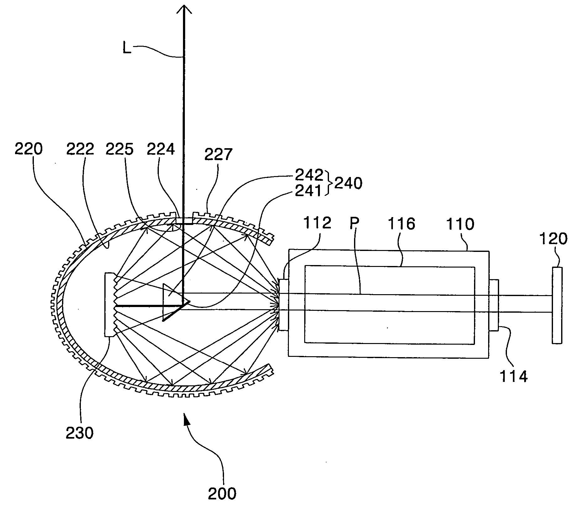
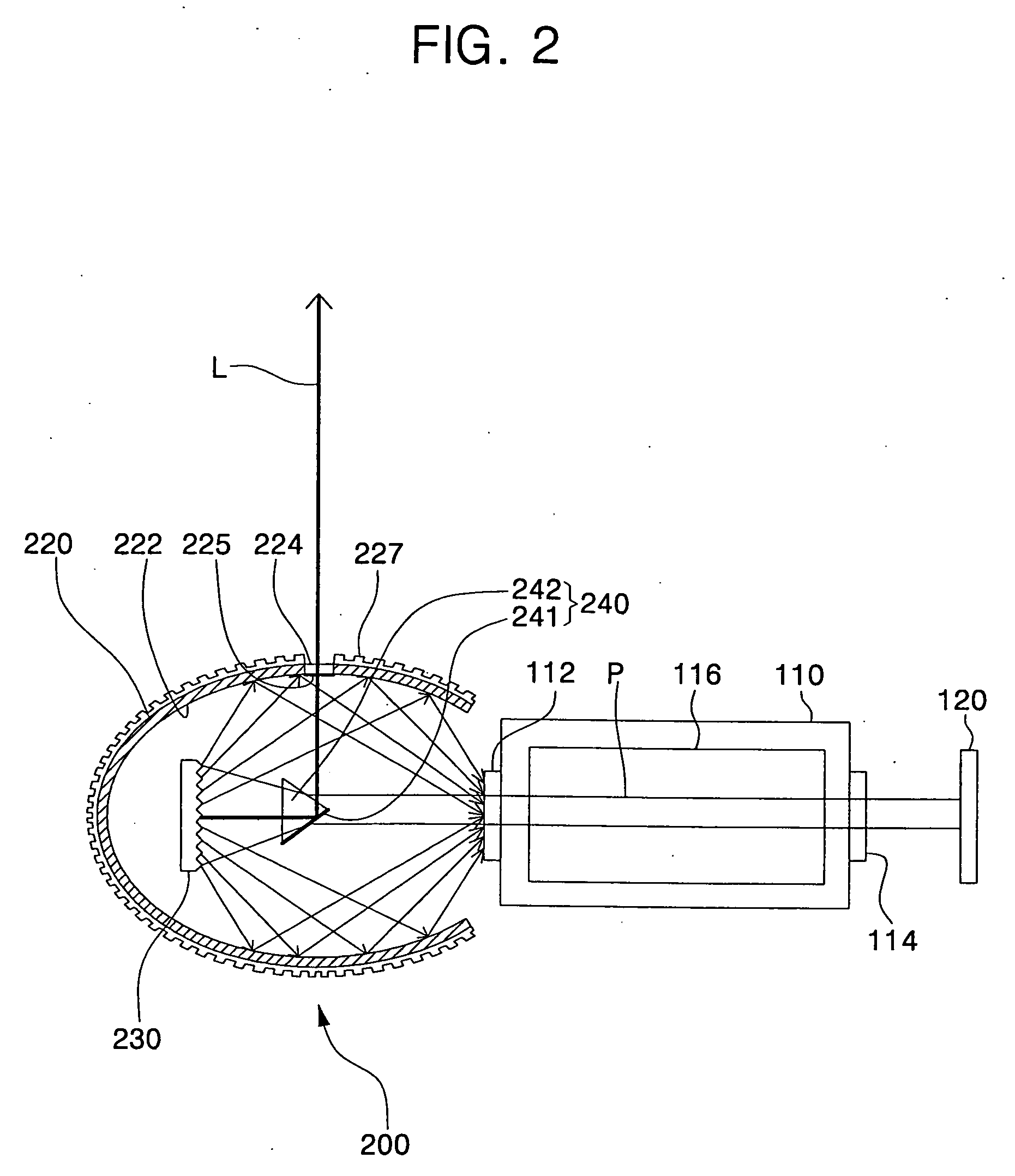
[0027] First, referring to FIG. 2, a light source of an exposure apparatus in accordance with the present invention generally includes a laser oscillator 110 for generating a laser beam, a line narrowing module 200 for reducing the bandwidth of a fraction of the laser beam introduced into the module through a front window 112 of the laser oscillator 110, and a laser beam returning unit 120 for returning to the laser oscillator 110 a fraction of the laser beam emitted through a rear window 114 of the laser oscillator 110.

[0028] The laser oscillator 110 excites laser gas, for example, a mixture of gases including a noble gas such as Kr, Ar or Ne, and a halogen including fluorine (F), using a laser beam or an electric discharge. For example, the laser oscillator 110 is filled with a gas mixture i...


PUM


Abstract

A line narrowing module includes an elliptical mirror having first and second foci and having an opening adjacent to the second focus, a diffraction grating disposed at the first focus so as to separate an incident beam into different lines, and a laser beam dispersion and extraction unit. The laser beam dispersion and extraction unit is situated in the module and composed to disperse a laser beam, incident thereon from a region containing the second focus of the elliptical mirror, over the diffraction grating and selectively extract from the resulting lines a laser beam having a desired narrowed bandwidth. Most of the remainder of the light is reflected by the elliptical mirror to the region having the second focus. A light source that employs the line narrowing module also includes a laser oscillator for generating the beam whose bandwidth is narrowed by the module, and light returning unit that returns one fraction of the beam extracted fron the laser oscillator back to the laser oscillator. Another fraction of the beam is extracted from the laser oscillator through a front window of the laser oscillator, and undergoes line narrowing in the module. The laser beam having the narrowed bandwidth is immediately output as the exposure light from the module, whereas the remainder of the light is returned from the module back to the laser oscillator.

Description

BACKGROUND OF THE INVENTION [0001] 1. Field of the Invention [0002] The present invention relates to an exposure apparatus of photolithography equipment used in the manufacturing of semiconductor devices and the like. More particularly, the present invention relates to a light source of the exposure apparatus having a line narrowing module. [0003] 2. Description of Related Art [0004] Photolithography equipment is used to form patterns, e.g. circuit patterns, on a substrate in the manufacturing of semiconductor devices and the like. An exposure apparatus of the photolithography equipment generally includes a reticle that defines a pattern to be transferred to a resist on the substrate, a light source for illuminating the reticle with an exposure light such that an image of the reticle pattern is picked up by the exposure light, and a projection lens for focusing the exposure light onto the resist on the substrate. Today's semiconductor devices are being made with increasingly higher ...

Claims


Application Information

Patent Timeline
Patent Type & Authority Applications(United States)
IPC IPC(8): H01S3/10
CPCG03F7/70025G03F7/70575H01S3/2256H01S3/08009H01S3/225H01S3/0401H01L21/0275
Inventor KIM, JANG-SUN
Owner SAMSUNG ELECTRONICS CO LTD
Why Eureka
Try Eureka