
Hydrogen generator

a generator and hydrogen technology, applied in the field of hydrogen generators, can solve the problems of high cost, high electrical power, and technological challenges, and achieve the effects of high strength, cost-effective containment solutions, and high efficiency

Inactive Publication Date: 2007-02-15
ARDICA TECH
View PDF44 Cites 56 Cited by
  • Summary
  • Abstract
  • Description
  • Claims
  • Application Information

AI Technical Summary

Benefits of technology

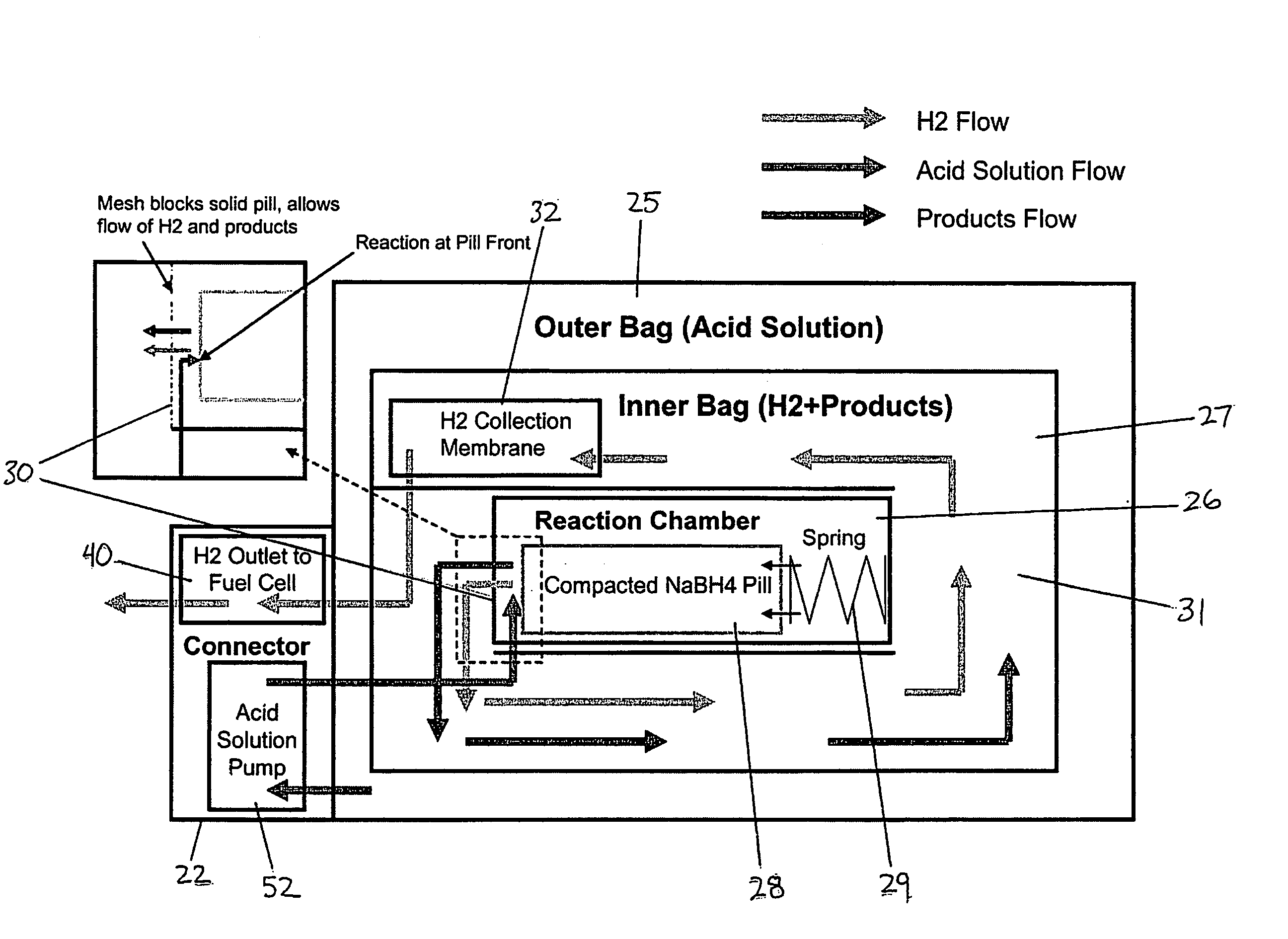
[0005] It is an object of the invention to provide an improved means for generating hydrogen gas. According to one aspect of the invention, there is provided a hydrogen gas generator that generates hydrogen gas by mixing at least two reactants. The generator can be a fuel cartridge especially useful for supplying hydrogen gas to a fuel cell system. The generator has a reaction chamber for receiving a solid reactant. The chamber has a reaction product separator impermeable to the solid reactant and a biasing means for bia

Problems solved by technology

Modern portable electronic devices are demanding increasing amounts of electrical power and chemical batteries are often the performance bottleneck for such devices.
Fuel cells are typically fuelled by hydrogen gas, but there are technological challenges in storing and delivering hydrogen gas to the fuel cells in a cost effective and efficient manner.
One particular challenge is to provide a fuel supply that is inexpensive, safe, light and compact enough to be readily portable yet store enough hydrogen to provide a useful amount of fuel to the fuel cell.
Both approaches have drawbacks; for example, metal hydride storage is relatively safe but has a low energy density to weight ratio, and compressed hydrogen storage can have a high energy density to weight ratio but requires high strength and expensive containment solutions.
Research has been conducted into using liquid methanol as a fuel and designing a “direct methanol” fuel cell that electrochemically produces electricity directly from methanol; however, significant technological challenges exist such as preventing methanol cross-over through the electrolyte membrane, and preventing catalyst poisoning by the methanol fuel.
While this approach is promising, technological challenges exist in containing the caustic fuel solution and preventing leakage, especially when the portable fuel cell system will be used in close proximity to humans.

Method used


Image

  • Hydrogen generator
  • Hydrogen generator
  • Hydrogen generator

Examples


Embodiment Construction

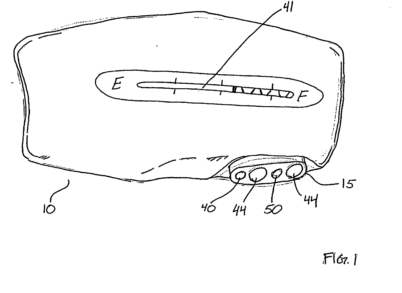
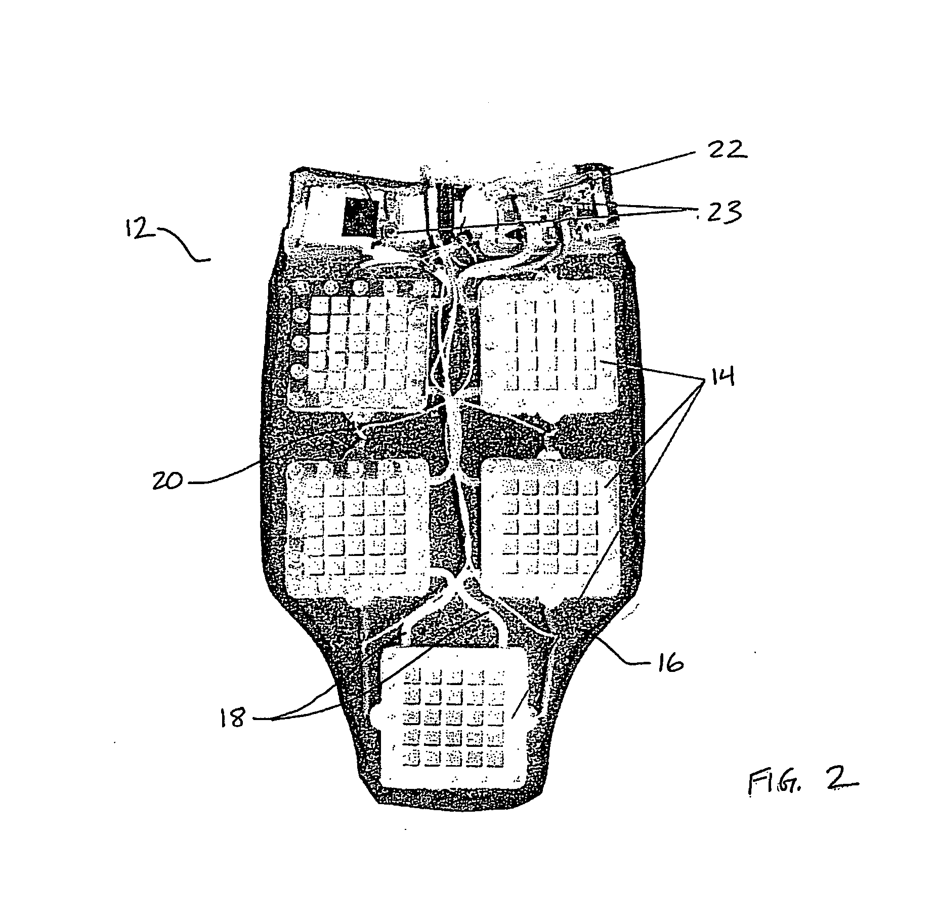
[0016] According to one embodiment of the invention and referring to FIG. 1, a portable fuel cartridge 10 generates hydrogen gas for use as fuel by a fuel cell. Referring to FIG. 2, a portable fuel cell system 12 comprises fuel cells 14 which generate electricity by electrochemically reacting hydrogen gas and oxygen in ambient air. The by-products of the electrochemical reaction also include water and heat. The generated electricity can be used to power portable electrical devices, and to provide heat. The portable fuel cartridge 10 has a connector sub-assembly 15 for physically and fluidly coupling the fuel cell cartridge 10 to the fuel cell system 12. Once coupled, hydrogen gas generated by the fuel cartridge 10 can be delivered into the fuel cell system 12 for use by the fuel cells 14.

[0017] One particular use contemplated for the fuel cartridge 10 and fuel cell system 12 is to provide heat and electrical power to personal apparel, such as a jacket. The fuel cell system 12 shown...


PUM


Abstract

A hydrogen gas generator generates hydrogen gas by mixing two reactants. The generator has a reaction chamber for receiving a solid reactant. The chamber has a reaction product separator impermeable to the solid reactant and a biasing means for biasing reactant products against the separator. The generator also has a liquid reactant dispenser for storing a liquid reactant and is fluidly coupled to the reaction chamber, such that dispensed liquid reactant reacts with the solid reactant in the reaction chamber to produce hydrogen gas and a waste product that are substantially permeable through the separator. The generator also has a product collector coupled to the reaction chamber for collecting hydrogen gas and waste product that have passed through the separator.

Description

FIELD OF THE INVENTION [0001] This invention relates generally to hydrogen generation and in particular, to a hydrogen generator that generates gaseous hydrogen by mixing at least two reactants. BACKGROUND OF THE INVENTION [0002] Modern portable electronic devices are demanding increasing amounts of electrical power and chemical batteries are often the performance bottleneck for such devices. Wireless products, such as personal digital assistants, mobile phones, entertainment devices, and next generation laptops in particular have a great demand for sustained power. For long-term portable operations, fuel cells are an attractive solution. Fuel cells, like batteries, efficiently convert chemical energy into electricity, but have additional advantages, such as higher energy density and the capability for instant refuelling. Fuel cells are typically fuelled by hydrogen gas, but there are technological challenges in storing and delivering hydrogen gas to the fuel cells in a cost effecti...

Claims


Application Information

Patent Timeline
IPC IPC(8): C01B3/02B01J8/08
CPCB01J7/02Y02E60/362C01B3/065Y02E60/36
Inventor FISHER, TOBIN JOSEPHTHOMAS, JESSE
Owner ARDICA TECH
Learn More