Compact thermal exchang unit of thermo-electric cooling mode using heat pipe

a heat pipe and thermo-electric cooling technology, applied in the direction of refrigeration machines, cooling/ventilation/heating modifications, and modifications for standard racks/cabinets, etc., can solve the problems of lager size of the overall communication system, device out of order, and conventional heat sinks that cannot no longer effectively perform radiation, etc., to enhance effectively radiating inside heat, and enhancing radiation ability per unit volume

Active Publication Date: 2007-02-22
TRANSPACIFIC SONIC
View PDF13 Cites 13 Cited by
  • Summary
  • Abstract
  • Description
  • Claims
  • Application Information

AI Technical Summary

Benefits of technology

[0018] The present invention enhances the radiation ability per unit volume by applying high-density fin stack to the thermo-electric cooling technology which has the Peltier Effect and effectively radiates the inside heat generated from the housing of the open-air communication device.
[0019] In addition, since the radiation ability per unit volume is enhanced, the size of the heat exchanger and the housing can be reduced. The heat pipes can be freely allocated free, wherein the space around the heat exchanger can be used more efficiently. While the conventional arts use a high capacity TEC device in case the heat sink cannot be enlarged, the present invention does not need to use the high capacity TEC device and economizes electric power since the radiation ability of the fin stack is excellent.

Problems solved by technology

This results in the lager size of the overall communication system.
If they do not radiate the heat, then the devices will become out of order due to the breakdown or shortage caused by the heat.
However, since the frequency bands are enlarged into the super high frequencies due to the augmentation of the traffic and the communication devices become highly integrated, leaner and lighter, the conventional heat sink could no longer effectively perform the radiation.
If so, however, the height, thickness and pitch of a fin become limited.
Therefore, the radiation area is limited and the radiation ability per unit volume becomes low.

Method used


Image

  • Compact thermal exchang unit of thermo-electric cooling mode using heat pipe
  • Compact thermal exchang unit of thermo-electric cooling mode using heat pipe
  • Compact thermal exchang unit of thermo-electric cooling mode using heat pipe

Examples


Embodiment Construction

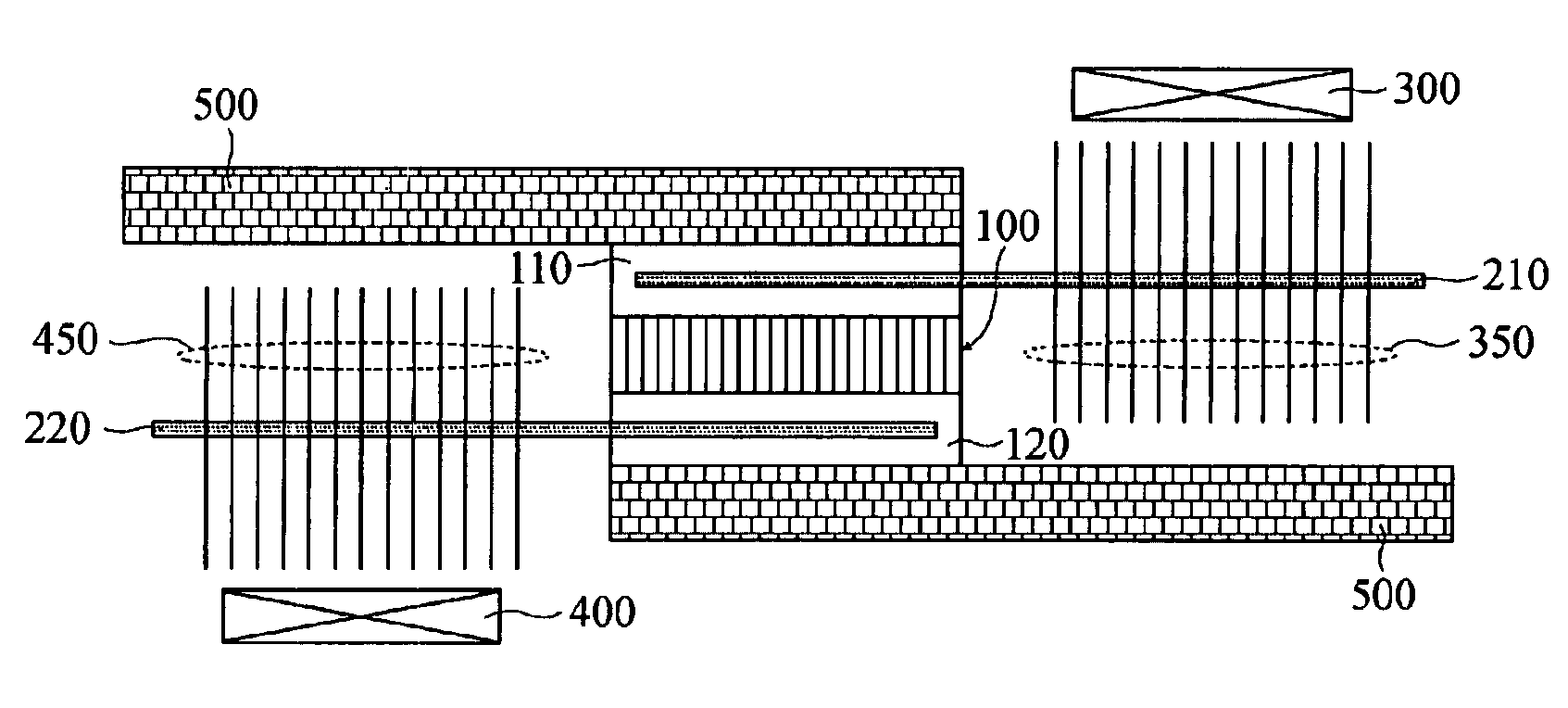
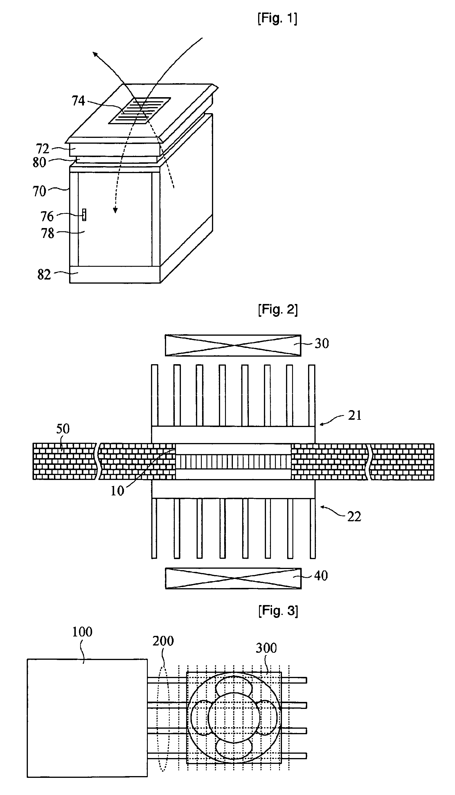
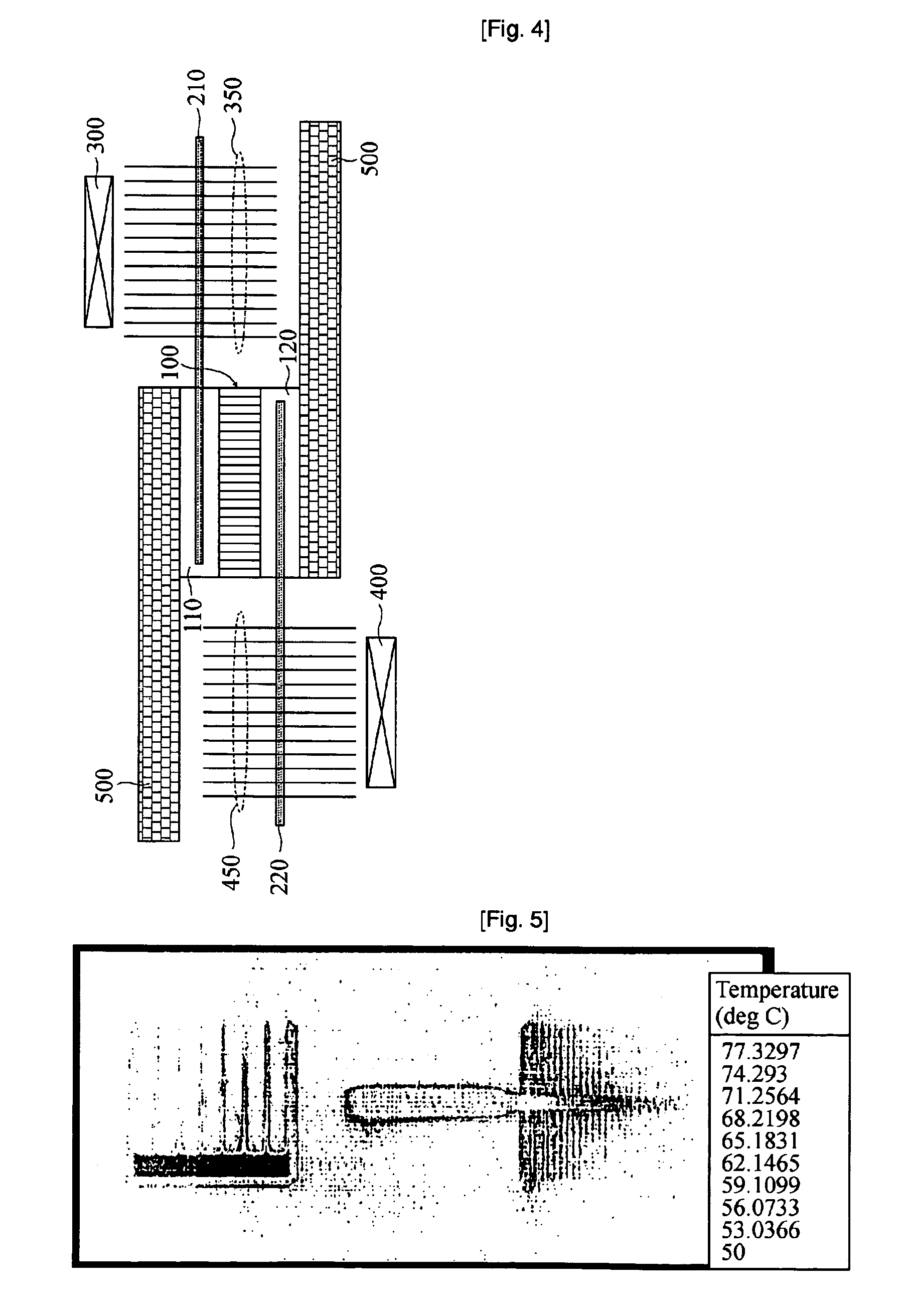
[0025]FIGS. 3 and 4 depict the structure of the present invention to which heat pipes are applied.

[0026] As shown therein, the plates (110, 120) formed in the center of the TEC heat exchanger, considering the thermal transmission area, are formed on an upper side and a lower side of the unit. The housing wall (500) is formed on an upper side and a lower side of the plates.

[0027] A plurality of heat pipes (210, 220) are directly inserted into the center of each plate, wherein the heat pipes (210) are formed on the right and the heat pipes (220) are formed on the left. A thin high-density fin stack (350) is formed for the heat pipes (210) to be centered on the fin stack (350). Further, an external fan (300) for processing an outside air is formed on an upper side of the fin stack (350). A thin high-density fin stack (450) is formed for the heat pipes (220) to be centered on the fin stack (450). Also, an internal fan (400) for processing an inside air is formed on a lower side of the...


PUM


Abstract

The present invention relates to a thermal exchange device using heat pipes to effectively discharge heat from inside of an open-air communication system. The present invention provides a plurality of heat pipes directly inserted between the plates of the thermo-electric cooling unit for accommodating a plurality of fins thereon. According to the structure suggested by the invention, since the heat pipes can be placed laterally with the thermo-electric cooling unit, the size of the overall communication system can be reduced with the same discharge capability.

Description

TECHNICAL FIELD [0001] The present invention relates to a thermal exchange device using heat pipes to effectively discharge heat from inside of an open-air communication system. BACKGROUND ART [0002] In a conventional thermal exchange device, a heat sink, which has a plurality of fins and is attached to the top and bottom plates of a thermo-electric cooling unit, has been widely used. In order to obtain a sufficient capability for discharging heat from inside of the communication system, the height and pitch of the fins at the heat sink rust increase in size. This results in the lager size of the overall communication system. [0003] In general, electronic devices or communication devices radiate heat by using a radiation equipment. If they do not radiate the heat, then the devices will become out of order due to the breakdown or shortage caused by the heat. [0004] An open-air communication system (e.g., a base station, a subscriber network and a traffic controller) adopts the method...

Claims


Application Information

Patent Timeline
Patent Type & Authority Applications(United States)
IPC IPC(8): F25B21/02H04B1/036H05K7/20
CPCF25B2321/0251H05K7/206H04B1/036F28D15/0275
Inventor LEE, DONG GYU
Owner TRANSPACIFIC SONIC
Why Eureka
Try Eureka