Heat exchanger unit and method of manufacturing the same

a technology of heat exchanger and heat exchanger plate, which is applied in the direction of laminated elements, semiconductor/solid-state device details, lighting and heating apparatus, etc., can solve the problems of difficult to change the space between adjacent tubes, manufacturing costs are likely to increase, so as to achieve easy and proper joining, easy holding of the flange, and reduced manufacturing costs

Inactive Publication Date: 2007-02-22
DENSO CORP
View PDF9 Cites 32 Cited by
  • Summary
  • Abstract
  • Description
  • Claims
  • Application Information

AI Technical Summary

Benefits of technology

[0016] Since the outer pipe section has the flange, the brazing material is easily held by the flange while the inner pipe section is inserted in the outer pipe section. Furthermore, the brazing material can easily flow between the outer side wall of the inner pipe section and the inner side wall of the outer pipe section. Accordingly, the adjacent

Problems solved by technology

As such, manufacturing costs are likely to increase.
Therefore, it is difficult to change spaces between adjacen

Method used


Image

  • Heat exchanger unit and method of manufacturing the same
  • Heat exchanger unit and method of manufacturing the same
  • Heat exchanger unit and method of manufacturing the same

Examples


first example embodiment

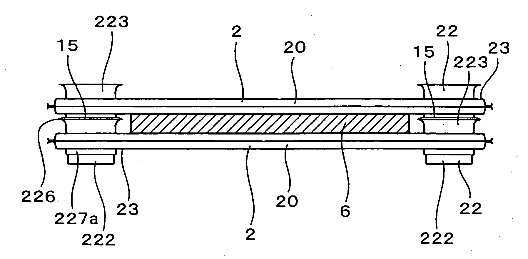
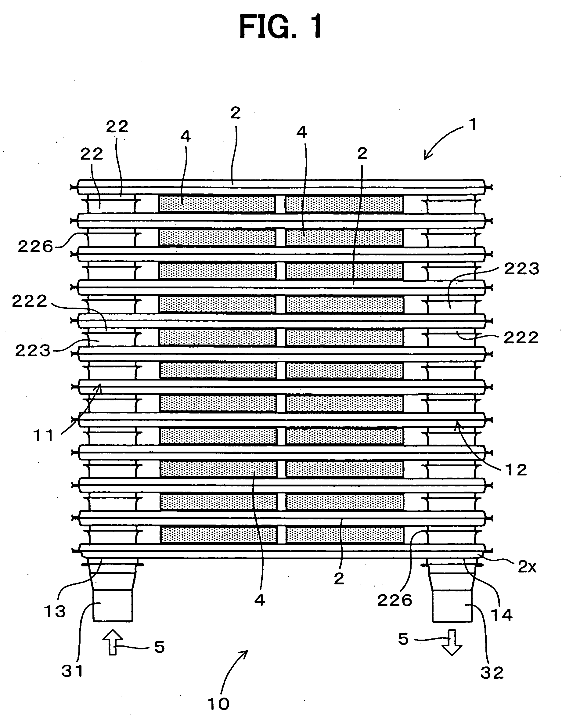
[0040] A first example embodiment of a heat exchanger unit 10 will be described with reference to FIGS. 1 through 11. The heat exchanger unit 10 of the first example embodiment has a heat exchanger 1 through which a heat medium 5 flows. The heat exchanger unit 10 performs heat exchange between the heat medium 5 and a heat exchanging object existing between tubes 2 of the heat exchanger 1. For example, electronic components 4 are disposed between the tubes 2 as the heat exchanging object. This heat exchanger unit 10 for example constructs a part of a power conversion apparatus.

[0041] As shown in FIG. 1, the heat exchanger 1 is formed of a stack of tubes 2. The electronic components 4 are arranged between the adjacent tubes 2. Each of the electronic components 4 has a flat rectangular parallelepiped shape. The electronic component 4 for example includes a power element therein for controlling high power. Although not illustrated, an electrode for power supply extends from one of long...

second example embodiment

[0091] Next, a second example embodiment of the heat exchanger unit 10 will be described with reference to FIG. 12. The outer plates 27, the middle plate 28 and the inner fins 29 of the tube 2 are made of the following metal plates.

[0092] The outer plate 27 has a core 271 made of aluminum. The outer surface of the outer plate 27 is defined by a bare surface 274 of the core 271. That is, the aluminum of the core 271 is bared to the outside of the tube 2.

[0093] As the material for the core 271, another material such as copper (including copper alloy) may be used, in place of aluminum (including aluminum alloy) However, aluminum is preferably used in view of efficiency, corrosion resistance, weight, and the like.

[0094] The outer plates 27 are joined to the middle plate 28 such that inner surfaces of the ends of the outer plates 27 contact the surfaces of the ends of the middle plate 28. Namely, the ends of the middle plate 28 are held between the ends of the outer plates 27. The mid...

third example embodiment

[0100] Next, a third example embodiment of the heat exchanger unit 10 will be described with reference to FIG. 13. As shown in FIG. 13, the outer plate 27 is made of a brazing sheet having the core 271 and a sacrificial anode material 273 on an inner surface.

[0101] As the sacrificial anode material 273, a metal material in which zinc is added to aluminum is used, for example. In this case, because the corrosion of the core 271 of the outer plate 27 is restricted by selectively corroding the sacrificial anode material 273, the material of the core of the inner fin 29 is not always necessary to contain zinc.

[0102] The outer surface of the outer plate 27, which makes contact with the electronic components 4, is the bare surface 274, similar to the second example embodiment. Further, the core of the inner fin 29 is made of a material having a potential (corrosion potential) higher than that of the sacrificial anode material 273. For example, the core of the inner fin 29 has a potentia...


PUM


Abstract

A heat exchanger unit has tubes each having a body section and at least one of an inner pipe section and an outer pipe section extending from the body section and defining an opening at an end. Each of the inner pipe section and the outer pipe section has a first portion and a second portion adjacent to the first portion. The tubes are stacked such that the body sections are spaced from each other. Further, the inner pipe section is received in the outer pipe section such that the first portion of the inner pipe section overlaps the first portion of the outer pipe section, and the second portions of the inner and outer pipe sections are located on opposite sides of the overlapped first portions. The first and second portions of the inner pipe section have an outer diameter smaller than an inner diameter of the first and second portions of the outer pipe section.

Description

CROSS REFERENCE TO RELATED APPLICATION [0001] This application is based on Japanese Patent Application No. 2005-238869 filed on Aug. 19, 2005, the disclosure of which is incorporated herein by reference. FIELD OF THE INVENTION [0002] The present invention relates to a heat exchanger unit and a method of manufacturing the same. BACKGROUND OF THE INVENTION [0003] For example, a stacked-type heat exchanger unit 9 shown in FIG. 20 is known. In the heat exchanger unit 9, electronic components 4 are arranged between the tubes 92 to be cooled by a heat medium flowing in the tubes 92 through side surfaces thereof. This kind of heat exchanger unit is for example disclosed in Japanese Patent Publication No. 2001-320005. [0004] In the heat exchanger unit 9, ends of the tubes 92 are connected to a first header 94 and a second header 95. Because the first header 94 and the second header 95 are provided as individual parts, the number of parts increases. As such, manufacturing costs are likely to...

Claims


Application Information

Patent Timeline
IPC IPC(8): F28F1/10
CPCF28D1/0333F28D1/0366F28D2021/0029F28F3/025H01L23/473H01L2924/0002F28F2240/00H01L2924/00
Inventor INAGAKI, MITSUHARUABEI, JUNGOCHO, KENTAIKEDA, TAKAOSHOJI, TOSHIYUKIMARUO, SHIZUO
Owner DENSO CORP
Why Eureka
Try Eureka