Radial flow micro-channel heat sink with impingement cooling

a micro-channel heat sink and radial flow technology, applied in indirect heat exchangers, stoves or ranges, lighting and heating equipment, etc., can solve the problem of relatively low air heat capacity and achieve the effect of enhancing the cooling of electronic components

Inactive Publication Date: 2007-02-22
COOLIT SYSTEMS INC
View PDF9 Cites 16 Cited by
  • Summary
  • Abstract
  • Description
  • Claims
  • Application Information

AI Technical Summary

Benefits of technology

[0011] Accordingly, the subject invention provides a heat sink assembly that optimizes the cooling fin arrangement to enhance cooling of an electronic component.

Problems solved by technology

However, air has a relatively low heat capacity.

Method used


Image

  • Radial flow micro-channel heat sink with impingement cooling
  • Radial flow micro-channel heat sink with impingement cooling
  • Radial flow micro-channel heat sink with impingement cooling

Examples


Embodiment Construction

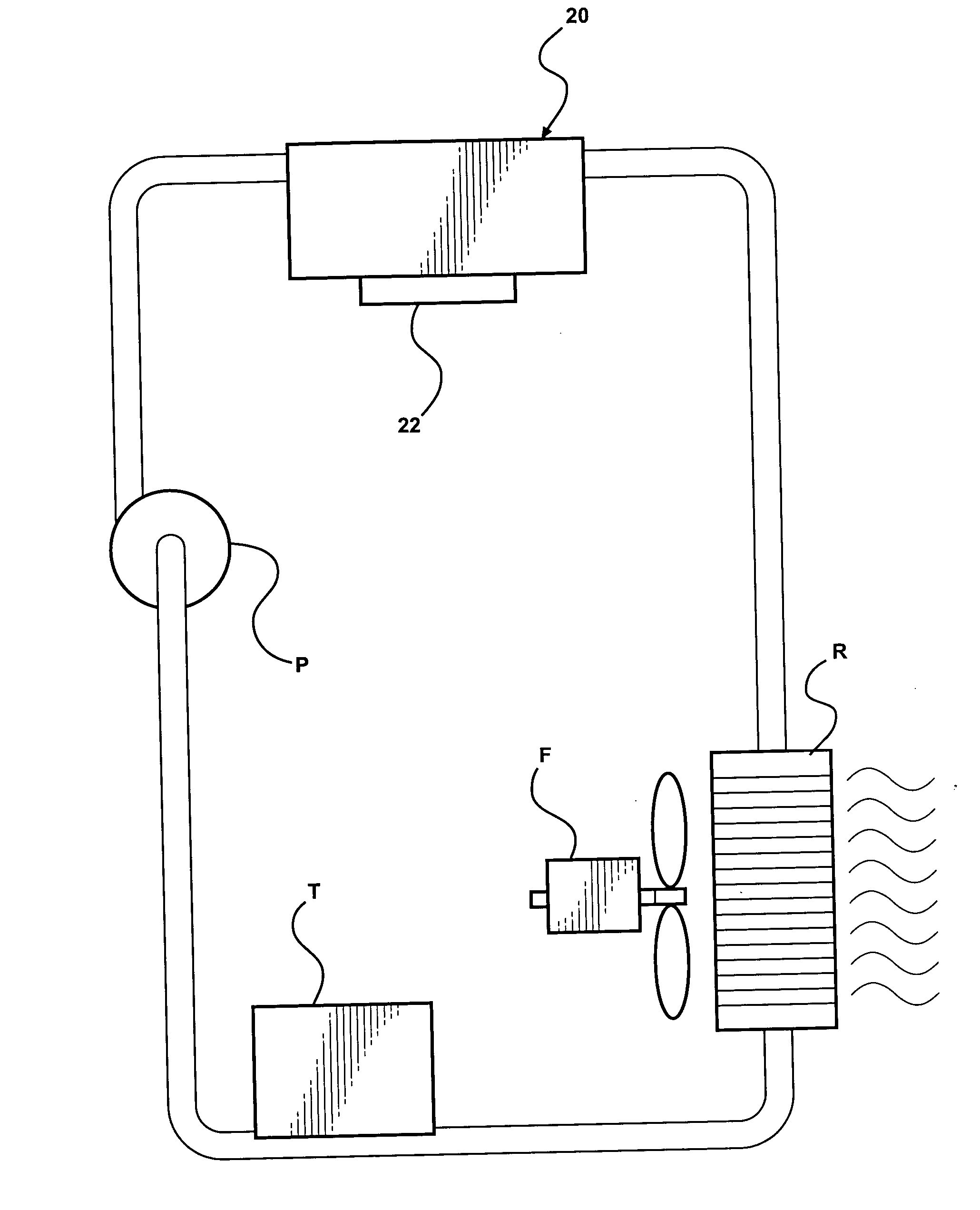
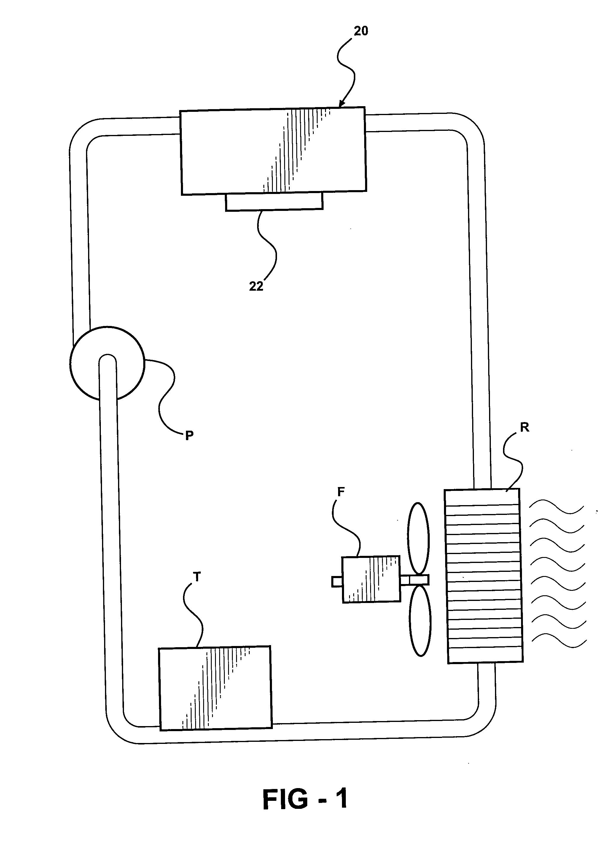
[0019]FIG. 1 illustrates a system incorporating the heat sink 20 of the subject invention into a liquid cooling system. The liquid cooling system includes working fluid mover, such as a pump P, creates a flow of cooling fluid, usually a liquid, through a cooling fluid storage tank T, which stores excess cooling fluid. The pump P moves the cooling fluid through a heat extractor assembly to dissipate heat from the cooling fluid. The heat extractor includes a fan F and a radiator R. The radiator R can be of the well known type including tubes with cooling fins between the tubes to exchange heat between the cooling fluid passing through the tubes and air forced through the radiator R by the fan F.

[0020] The heat sink 20 assembly removes heat from an electronic device 22.

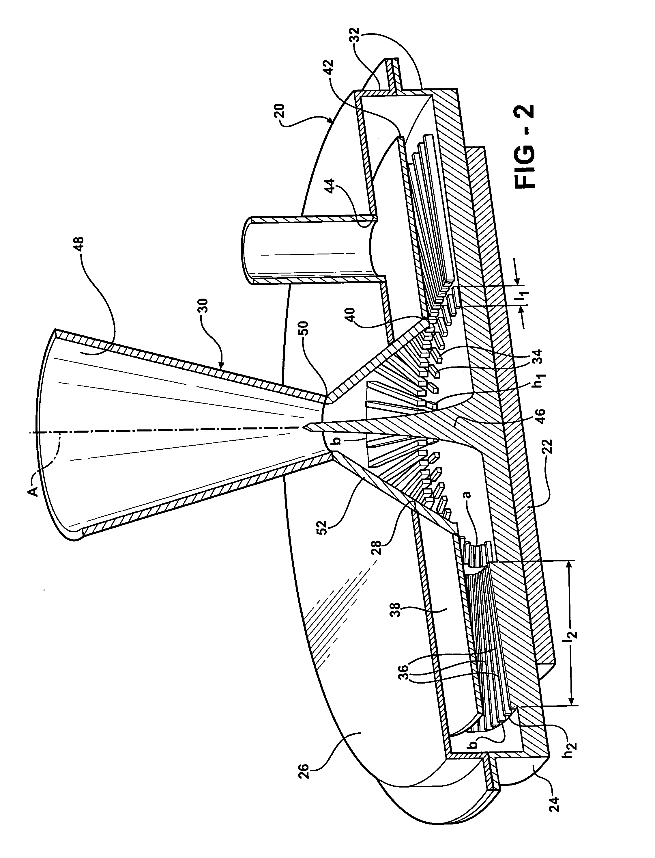
[0021] The essence of the heat sink 20 assembly is a housing having a base 24 with a top surface, a lid 26 with a bottom surface in spaced relationship with and parallel to the top surface of the base 24. The lid 26 de...


PUM


Abstract

A heat sink removes heat from an electronic device and comprises a base, a lid. An inner ring of first fins extend radially outwardly first length from an inner circle and extend axially a first height from the top surface of the base, and an outer ring of second fins extend radially inwardly a second length from an outer periphery and extend axially a second height from the top surface of the base. A confining plate extends radially above the fins and is spaced below the bottom surface of the lid whereby coolant fluid flows from an inlet opening of the lid through the center opening of the confining plate and radially outwardly through the fins and upward around the outer edge of the confining plate and into the space above the confining plate to an outlet opening. A nozzle having a throat is disposed above the lid and extends below the lid to the confining plate. A flow diverter extends upwardly from the top surface of the base and into and through the throat of the nozzle.

Description

BACKGROUND OF THE INVENTION [0001] 1. Field of the Invention [0002] The subject invention relates to a cooling assembly for cooling an electronic device such as a microprocessor or a computer chip. [0003] 2. Description of the Prior Art [0004] These electronic devices generate a high concentration of heat, typically a power density in the range of 5 to 35 W / cm2. Accordingly, research activities have focused on developing more efficient cooling assemblies capable of efficiently dissipating the heat generated from such electronic devices, while occupying a minimum of space. [0005] A forced air cooling assembly typically includes a heat exchanger and a heat sink, and cools the electronic device by natural or forced convection cooling methods. The electronic device is attached to the heat sink and transfers heat thereto. The heat exchanger typically uses air to directly remove the heat from the heat sink. However, air has a relatively low heat capacity. Such forced air cooling assemblie...

Claims


Application Information

Patent Timeline
Patent Type & Authority Applications(United States)
IPC IPC(8): H05K7/20
CPCH01L23/473H01L2924/0002H01L2924/00
Inventor GHOSH, DEBASHISBHATTI, MOHINDER SINGHREYZIN, ILYAPARISI, MARK JOSEPH
Owner COOLIT SYSTEMS INC
Why Eureka
Try Eureka