Clutch device

a technology of clutch elements and friction surfaces, which is applied in the direction of fluid-actuated clutches, non-mechanical actuated clutches, clutches, etc., can solve the problems of disadvantageous effects on the degree of utilization of friction surfaces in their current state for torque transmission, relatively hard engagement process and jolts, etc., to avoid thermal problems of clutch elements, particular uniformity and softness, and exclude disadvantageous effects of tolerances and waviness

Inactive Publication Date: 2007-02-22
ZF FRIEDRICHSHAFEN AG
View PDF6 Cites 24 Cited by
  • Summary
  • Abstract
  • Description
  • Claims
  • Application Information

AI Technical Summary

Benefits of technology

[0006] In clutch devices of this type, there is a problem between the contact point and the engaged position, namely, that the nonelastic piston arrives in working connection with friction surfaces of the friction clutch, which are also nonelastic, and accordingly a very short engagement distance is available for the buildup of torque transmission, called “modulation”. As a result, the engagement process is relatively hard and subject to jolts. In addition, radial and / or axial tolerances between the clutch elements as well as a possible waviness of the friction surfaces in the circumferential direction can have disadvantageous effects on the degree of utilization of the friction surfaces in their current state for the transmission of torque. These effects becoming manifest as an increase in the applied surface pressures in certain areas.
[0007] One object of the present invention is to design a clutch device in such a way that, while avoiding thermal problems with the clutch elements of the friction clutch, the disadvantageous effects of tolerances and waviness are excluded, while at the same time the clutch engages softly and uniformly.
[0008] When a torque-building or generating arrangement is associated with the pressure-exerting device, the modulation, that is the governing and / or control of the clutch-engaging process and thus the buildup of the transmission of torque between the contact point and the engaged position, will proceed with particular uniformity and softness, especially when the torque-building arrangement is designed with an axial force storage device serving as a contact spring, as a result of which additional elasticity is introduced between the pressure-exerting device and the minimum of one clutch element of the friction clutch. As a result, it is ensured that the individual contact surfaces of the clutch elements, such as the pressure-exerting device and the clutch element or several clutch elements, will make better adaptive contact with each other. Thus not only axial and / or radial tolerances between the individual clutch elements, but also any waviness which may be present in the area of the friction linings or friction surfaces of the clutch elements, can be compensated more effectively.
[0009] Because the torque-building arrangement uses the pressure-exerting device as a first support element and uses the clutch element as a second support element, it cannot be excluded that certain areas are created, namely, a first area between the pressure-exerting device and the torque-building arrangement and a second area between the latter and the clutch element, in which the torque-building arrangement generates a sealing effect and thus at least considerably reduces the flow-through of the fluid which is present in the cooling space which houses the friction clutch. Because both the pressure-exerting device and the clutch element are clutch components of the friction clutch, and because these components undergo heating, especially when there is slippage between a drive, such as the crankshaft of an internal combustion engine, and a takeoff, such as a gearbox input shaft, it is necessary to prevent this heat from leading to unwanted thermal stresses on the pressure-exerting device, on the fluid, and / or on the adjacent clutch disk. For this reason, a flow passage for fluid is provided in at least one of the support elements, i.e., on the pressure-exerting device and / or on the clutch element, through which, as a result of the relative rotational movement of the clutch elements with respect to each other, fluid is supplied to support the flow and thus to dissipate the heat from the support element in question.
[0010] In one embodiment, the flow passage can be designed in the form of grooves in the pressure-exerting device and / or in the adjacent clutch element, but it could just as well be in the form of openings between offset tongues on the circumference of the torque-building arrangement. The latter embodiment is especially advantageous when the torque-building arrangement has an axial force storage device, formed by a disk spring, which, proceeding from an essentially ring-shaped base body, carries the previously mentioned tongues on its inner and / or outer radial side.
[0011] When the torque-building arrangement includes a disk spring, the formation of a flow channel in at least one of the support elements is especially advantageous, because the disk spring is dosed on its radial sides and thus can be made thinner in cross section than a disk spring with tongues on at least one radial side. As a result, a space advantage is obtained, namely, in the comparatively narrow axial area between the pressure-exerting device and the adjacent clutch element.

Problems solved by technology

In clutch devices of this type, there is a problem between the contact point and the engaged position, namely, that the nonelastic piston arrives in working connection with friction surfaces of the friction clutch, which are also nonelastic, and accordingly a very short engagement distance is available for the buildup of torque transmission, called “modulation”.
As a result, the engagement process is relatively hard and subject to jolts.
In addition, radial and / or axial tolerances between the clutch elements as well as a possible waviness of the friction surfaces in the circumferential direction can have disadvantageous effects on the degree of utilization of the friction surfaces in their current state for the transmission of torque.

Method used


Image

  • Clutch device
  • Clutch device
  • Clutch device

Examples


Embodiment Construction

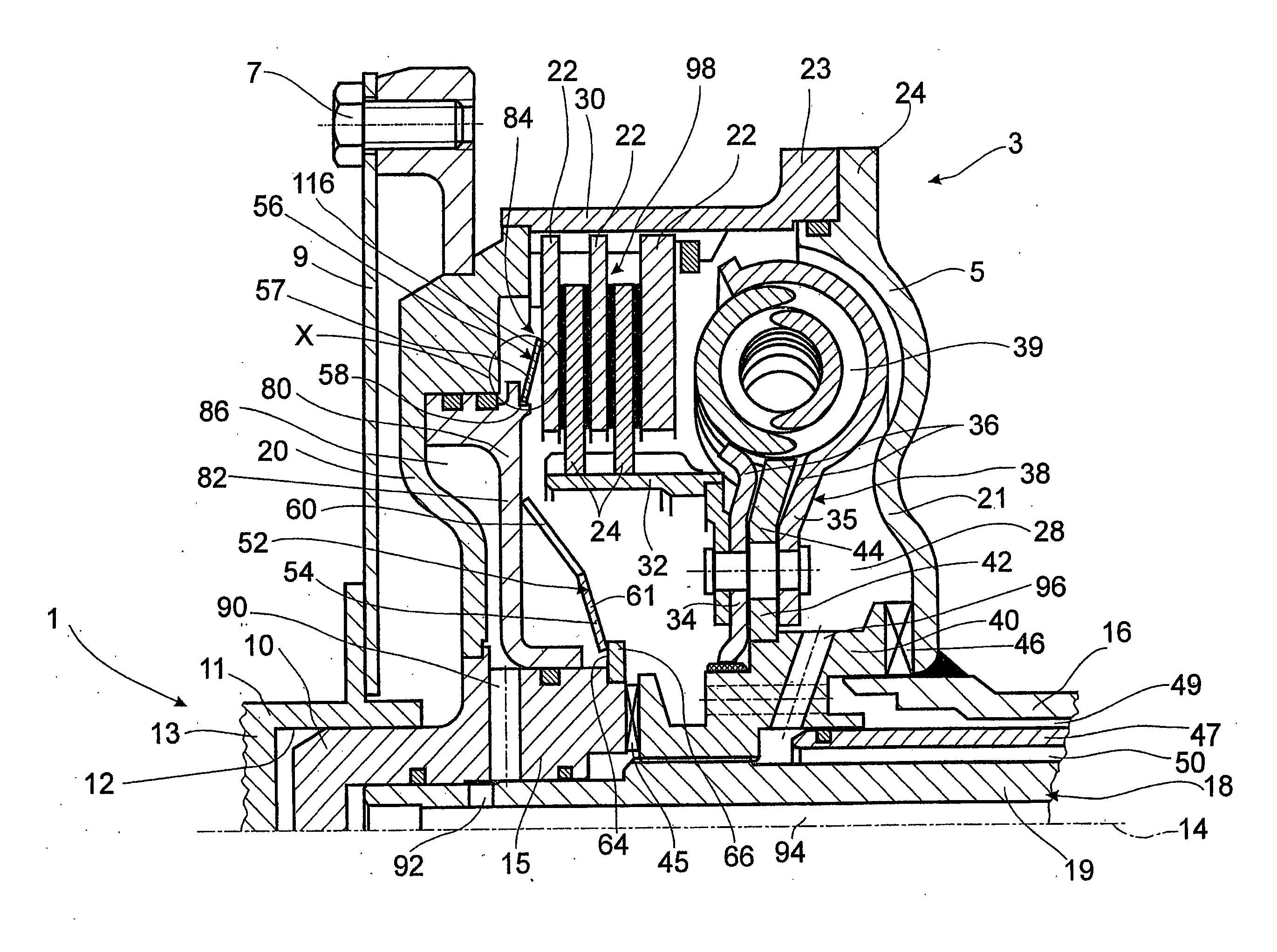
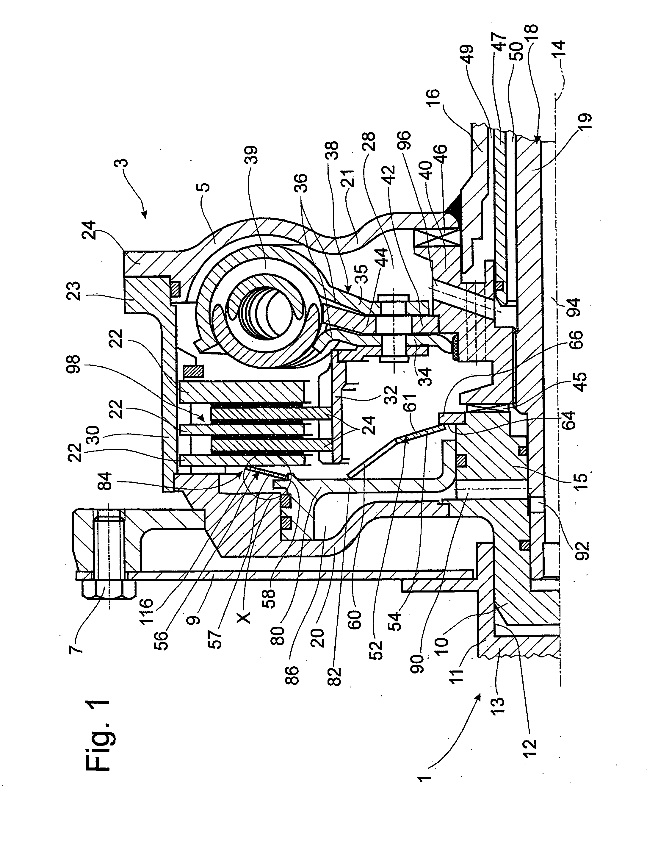
[0021]FIG. 1 shows a schematic diagram of a drive train 1 with a clutch device 3 of the present invention. The clutch device 3 comprises a housing 5, which can be connected for rotation together with a drive 11, such as the crankshaft 13 of an internal combustion engine, by means of a plurality of mounting elements 7 and a connecting element 9 such as a flexplate. In the area of an axis of rotation 14, the clutch device has a bearing journal 10 provided on a drive-side housing hub 15. The journal is mounted in a centering guide 12 formed on the drive 11. On the axial side facing away from the drive 11, the housing 5 has a takeoff-side housing hub 16, which is connected to, for example, a gearbox arrangement (not shown) and rotatably drives there a fluid-conveying pump (also not shown). A takeoff 18, the free end of which projects from the housing 5, is mounted concentrically with respect to the takeoff-side housing hub 16. This takeoff 18 can be formed by, for example, a gearbox inp...


PUM


Abstract

A clutch device has a housing connected to a drive; a takeoff, which is mounted with freedom of rotation in the circumferential direction relative to the housing; and at least one friction clutch, which is mounted in the housing and which can be shifted between an engaged position and a released position. The clutch has clutch components including at least one pressure-exerting device and at least one clutch element which can be actuated by the pressure-exerting device, both the clutch element and the pressure-exerting device being able to shift position to a limited extent in the axial direction. The clutch element has at least one friction surface and a clutch hub in working connection with the takeoff. Beginning at a point of contact between the engaged position and the released position and continuing until the engaged position is reached, the torque of the drive can be transmitted via the housing and the friction clutch to the takeoff, whereas on the other side of the contact point and continuing until the released position, this torque transmission is suspended. A torque-building arrangement, which exerts force on the pressure-exerting device in the direction pointing away from the clutch element of the friction clutch, is assigned to the pressure-exerting device. This torque-building arrangement uses the pressure-exerting device as a first support element on one side and the clutch element as a second support element on the other side. On at least one of these support elements and / or on the torque-building arrangement, at least one flow passage is provided for the fluid which is present in a cooling space inside the housing in which the friction clutch is disposed.

Description

BACKGROUND OF THE INVENTION [0001] 1. Field of the Invention [0002] The invention relates to a clutch device having a housing connected to a drive and a takeoff, mounted with freedom of rotation in the circumferential direction relative to the housing. [0003] At least one friction clutch is disposed within the housing and can be shifted between an engaged position and a disengaged or released position, and which has, as clutch components, at least one pressure-exerting device and at least one clutch element which can be actuated by the pressure-exerting device. The clutch element, like the pressure-exerting device, is free to shift its position to a limited extent in the axial direction and has at least one friction surface and a clutch hub in working connection with the takeoff, and wherein, beginning at a contact point between the engaged position and the released position and continuing until the engaged position is reached, the torque of the drive can be transmitted via the hous...

Claims


Application Information

Patent Timeline
Patent Type & Authority Applications(United States)
IPC IPC(8): F16D25/06
CPCF16D25/123F16D25/0638
Inventor SCHRODER, ARTHURLOTZE, RUDIGERSUDAU, JORG
Owner ZF FRIEDRICHSHAFEN AG
Why Eureka
Try Eureka