Hydroclone based fluid filtration system

Active Publication Date: 2007-02-22
ACCELERATED FILTRATION INC
View PDF13 Cites 48 Cited by
  • Summary
  • Abstract
  • Description
  • Claims
  • Application Information

AI Technical Summary

Benefits of technology

[0008] In one aspect of the invention, the filter has a plurality of steps each having a different diameter. The largest diameter step is positioned so that it is closest to the fluid inlet and the smallest diameter step is located generally near the effluent outlet. These steps help reduce the incidence of eddies and countercurrents within the hydroclone chamber. In some embodiments, the filter is arranged as a plurality of substantially circular stages, each stage having a successively smaller diameter. In another embodiment, a single spiral step is provided. The stepped filter is preferably a surface filter.
[0009] In another aspect of the invention, the filter is a surface filter, as for example, an electroformed metal surface filter. In some preferred embodiments, the openings in the surfac

Problems solved by technology

Many such technologies require a relatively large amount of physical space and/or require the use of consumable filters that add to operational costs.
Although hydroclones have been used to remove suspended particles from water in a variety of applications, existing hydroclones are generally no

Method used


Image

  • Hydroclone based fluid filtration system
  • Hydroclone based fluid filtration system
  • Hydroclone based fluid filtration system

Examples


Embodiment Construction

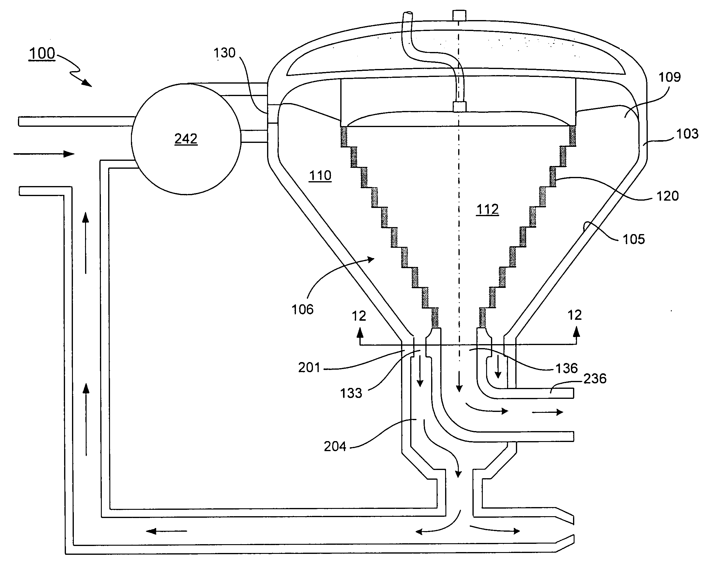
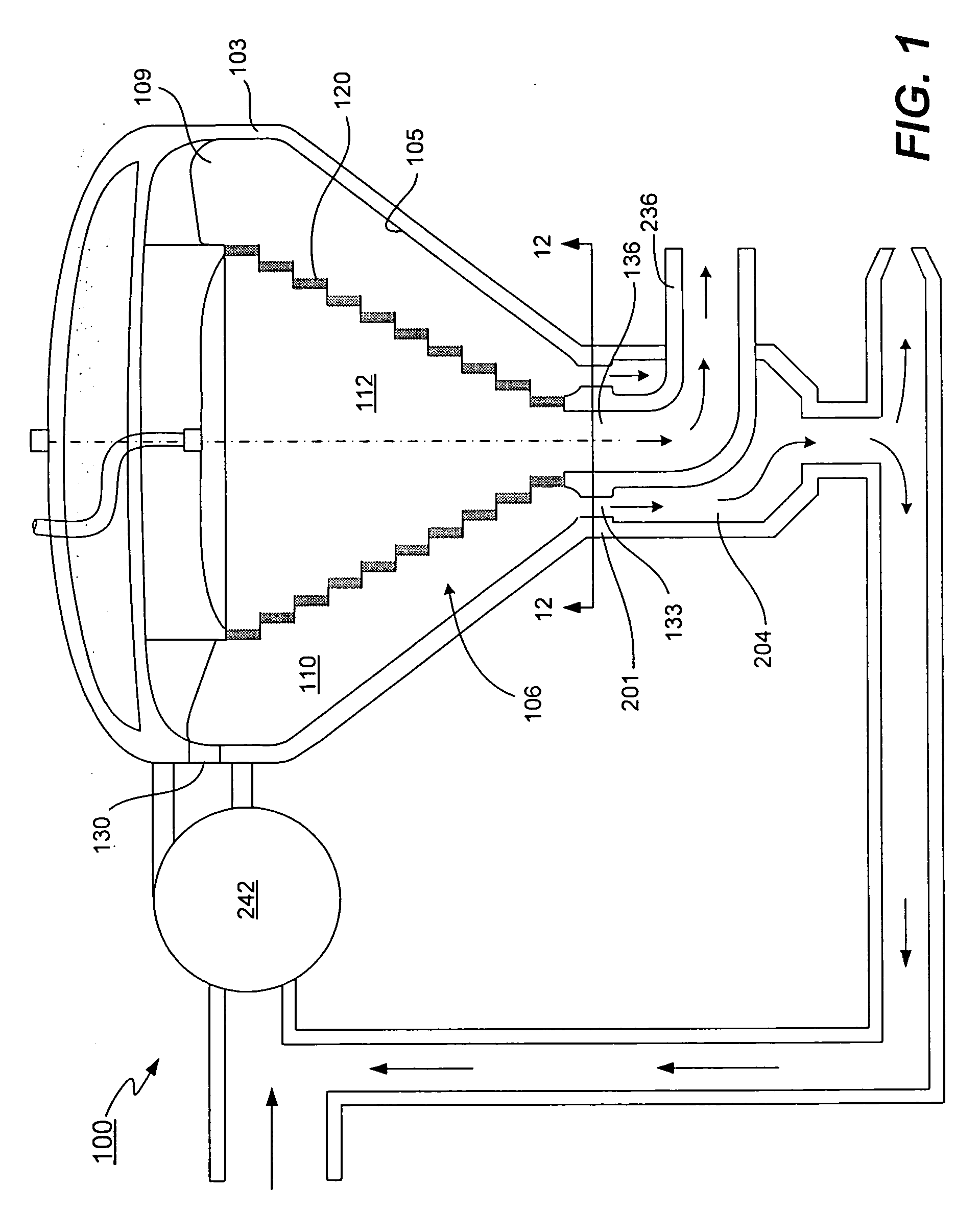
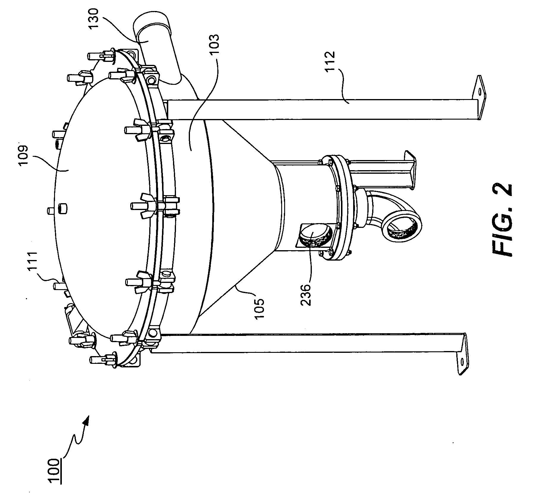
[0036] A hydroclone based filtration system in accordance with one embodiment of the present invention is diagrammatically illustrated in FIGS. 1-3. As seen therein, the hydroclone based filtration system 100 includes a housing 103 having chamber walls 105 and a lid 109. The chamber walls 105 define a tapered (frusto-conically shaped) fluid compartment 106 and the lid 109 covers the fluid compartment 106. The housing 103 is supported by a stand 112 that can take any suitable form. A stepped filter assembly 120 is positioned within the fluid compartment 106. As will be described in more detail below, the stepped filter assembly 120 may be substantially conically (frusto-conically) shaped as well and is positioned centrally within the fluid compartment 106 so that the filter is spaced apart from the peripheral chamber walls 105. The region between the chamber walls 105 and the filter assembly 120 is defined as a hydroclone chamber 110 and the region in the central region of the filter...


PUM


Abstract

A variety of improved hydroclone based fluid filtering systems are described. The hydroclones generally include a tank having an internal chamber and a filter (preferably a surface filter) that is positioned within the internal chamber. The filter defines a filtered fluid chamber within the internal chamber of the tank. The hydroclone may be operated such that a vortex of flowing fluid is formed between the chamber wall and the filter with the filter being located in the center of the vortex. With this arrangement, the filter acts as a cross-flow filter. In one aspect of the invention, the filter is a stepped filter. In another aspect of the invention, the filter is an surface filter, as for example, an electroformed metal surface filter. In some preferred embodiments, the openings in the filter are arranged as slots that extend substantially vertically so that they are oriented substantially perpendicular to the flow path of fluid flowing in the adjacent portion of the vortex. In another aspect of the invention, a circulating cleaning assembly is provided in the hydroclone region. The cleaning assembly is arranged to help clean the filter and is driven by the vortex of flowing fluid formed in the hydroclone region of the internal chamber. In yet another aspect of the invention, improved hydroclone intake structures are described. The described hydroclones may be used to filter water and other fluids in a wide variety of applications.

Description

[0001] This application claims priority of U.S. Provisional Application No. 60 / 709,868 filed Aug. 18, 2005, and U.S. Provisional Application No. 60 / 822,486 filed Aug. 15, 2006, both of which are incorporated herein by reference.BACKGROUND OF THE INVENTION [0002] The present invention generally relates to fluid filtering. More particularly, the invention relates to hydroclone based fluid filtration systems with cross flow filters. The described devices may be used in a variety of water treatment, fluid filtering and particle separation applications. [0003] A wide range of technologies are currently used to treat, purify and / or filter water. Many such technologies require a relatively large amount of physical space and / or require the use of consumable filters that add to operational costs. For example, many drinking water treatment applications utilize settling ponds in combination with a series of screens and filters of progressively decreasing pore size to remove suspended solid par...

Claims


Application Information

Patent Timeline
IPC IPC(8): C02F1/38
CPCB01D21/0003B04C2003/006B01D21/0012B01D21/2411B01D21/30B01D29/115B01D2201/02B01D2201/0415B04C3/06B04C9/00B04C2009/004C02F1/38C02F2301/024C02F2301/026B01D21/0006B01D29/908B01D29/62B01D21/2488B04C5/08B01D21/267B01D29/885B01D29/906B01D21/34
Inventor LEVITT, DAVID J.
Owner ACCELERATED FILTRATION INC
Why Eureka
Try Eureka