Plasma display apparatus

Inactive Publication Date: 2007-02-22
SAMSUNG SDI CO LTD +1
View PDF10 Cites 1 Cited by
  • Summary
  • Abstract
  • Description
  • Claims
  • Application Information

AI Technical Summary

Benefits of technology

[0008] It is therefore an object of the present invention t

Problems solved by technology

However, if the chassis base has smaller thickness, the chassis base may not be strong enough to support the panel.
Further, there is much effort to replace an expensive chassis base made out of aluminum with an inexpensive chassis base made out of synthetic resin.
However, even though the chassis bas

Method used


Image

  • Plasma display apparatus
  • Plasma display apparatus
  • Plasma display apparatus

Examples


Example

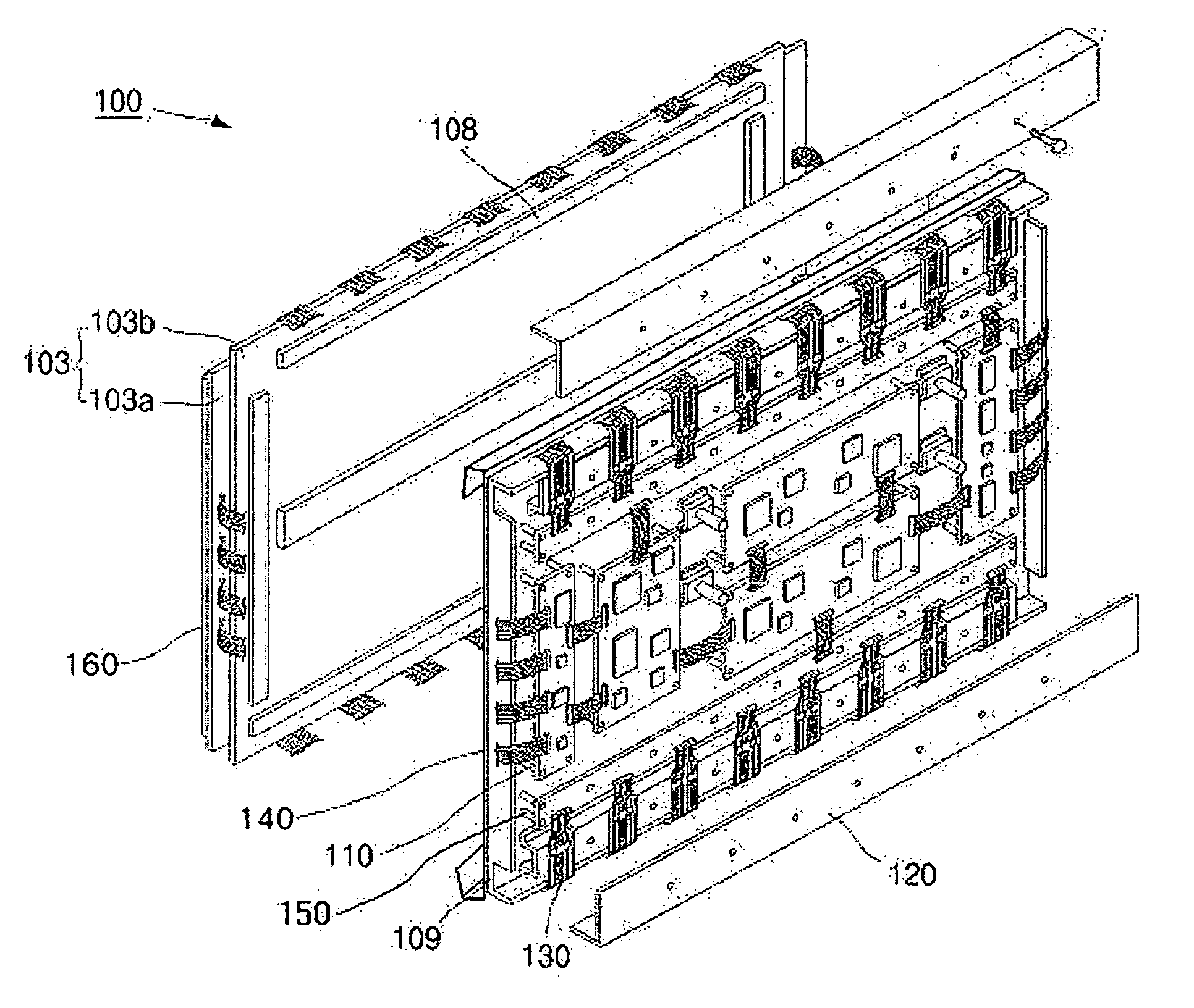
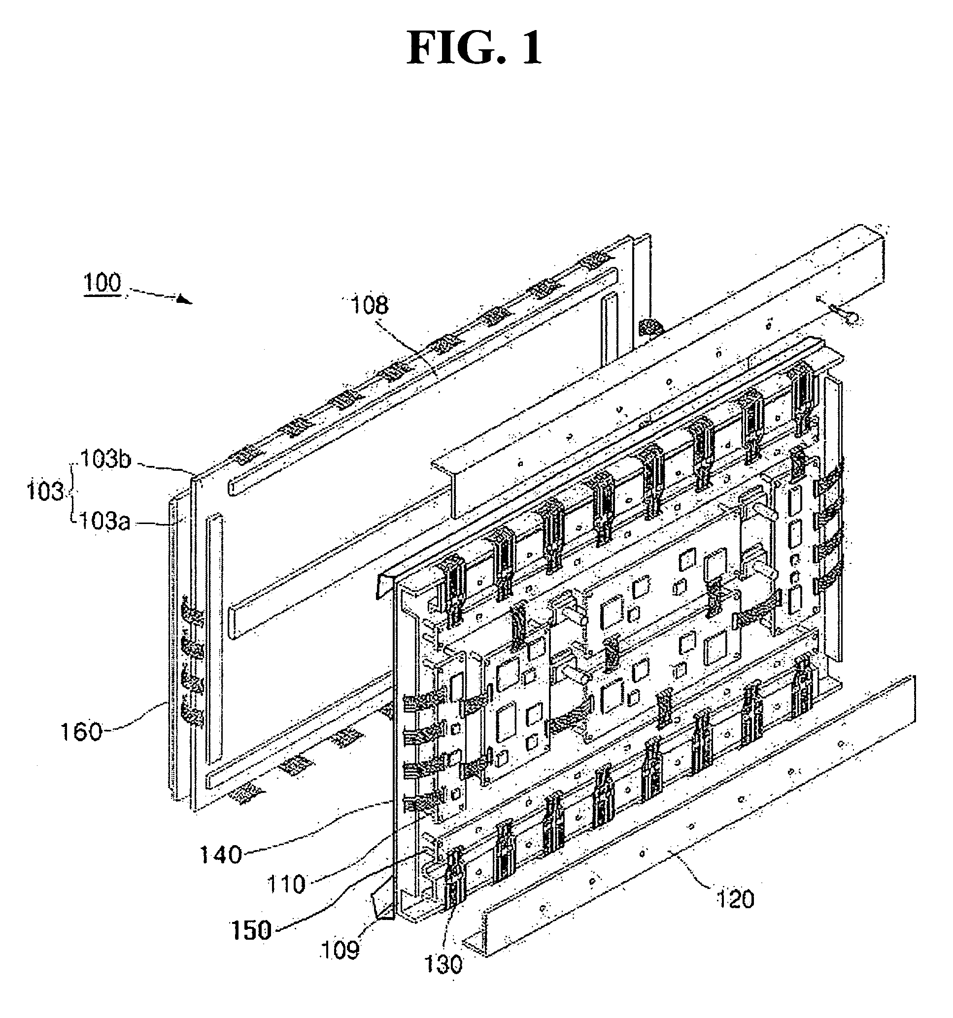
[0018] Turning now to the figures, FIG. 1 is an exploded schematic perspective view of a plasma display apparatus according to an embodiment of the present invention. Referring to FIG. 1, the plasma display apparatus 100 includes a panel 103, an adhesive member 108, a chassis base 109, a circuit portion 110, a protective plate 120, connection members 130, a thin metal plate 140, and a direct-attachment filter 160.

[0019] The panel 103 displays images by performing discharge depending upon operation signals transferred from a circuit element disposed on the circuit portion 110. The panel 103 has barriers, electrodes, a fluorescent material, a dielectric material, and a protective layer formed between two substrates 103a and 103b. Further, the panel 103 has discharge cells, which are defined by the substrates 103a and 103b, and the barriers. Within the discharge cells, the discharge occurs. These discharge cells are filled with inert gases which produce ultra-violet rays that excite t...


PUM


Abstract

A plasma display apparatus. The plasma display apparatus uses a synthetic resin chassis base. A thin metal plate is attached between the panel and the chassis base and is connected to grounded terminals of the circuit portion and to an electromagnetic wave blocking direct-attachment filter on a front of the panel. Such a structure is advantageous in that as the synthetic chassis base is employed in the plasma display apparatus, it is possible to reduce the amount of material used and to reduce molding costs, to simplify processes, and to decrease the weight and noise of a module. Second, the plasma display apparatus has another advantage of securing a ground for the circuit portion and improving the stability of the plasma display panel module, as the thin metal plate can be electrically connected to the direct-attachment filter and perform the grounding function.

Description

CLAIM OF PRIORITY [0001] This application makes reference to, incorporates the same herein, and claims all benefits accruing under 35 U.S.C. § 119 from an application for PLASMA DISPLAY APPARATUS earlier filed in the Korean Intellectual Property Office on 17 Aug. 2005 and there duly assigned Serial No. 10-2005-0075162. BACKGROUND OF THE INVENTION [0002] 1. Field of the Invention [0003] The present invention relates to a plasma display apparatus, and more particularly to a plasma display apparatus which has a chassis base made out of synthetic resin instead of a metal such as aluminum, resulting in reduced total weight, reduced number of parts used, reduced noise, and reduced manufacturing costs, while improving workability. A thin metal plate can also be present to serve as a thin grounding plate while improving the electric connection and the grounding performance of the circuit portion and the panel. [0004] 2. Description of the Related Art [0005] Recently, various flat display de...

Claims


Application Information

Patent Timeline
IPC IPC(8): H01J61/52G09F9/00
CPCH05K1/142H05K5/02H01J11/34H01J11/46
Inventor KIM, YEUNG-KI
Owner SAMSUNG SDI CO LTD
Why Eureka
Try Eureka