

Microwave generator
a technology of micro-wave generator and generator, which is applied in the direction of oscillator generator, magneton, pulse automatic control, etc., can solve the problems of difficult control of microwave amplitude, and the inability of conventional microwave generating apparatus to apply to plasma generating apparatus
- Summary
- Abstract
- Description
- Claims
- Application Information
AI Technical Summary
Benefits of technology
Problems solved by technology
Method used
Image

Examples
first embodiment
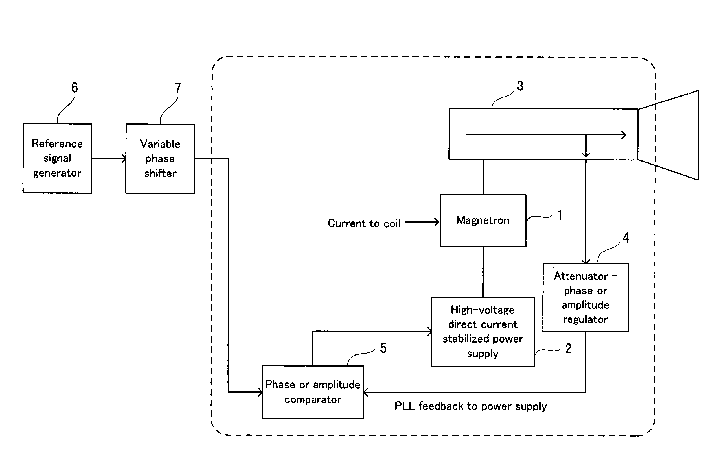
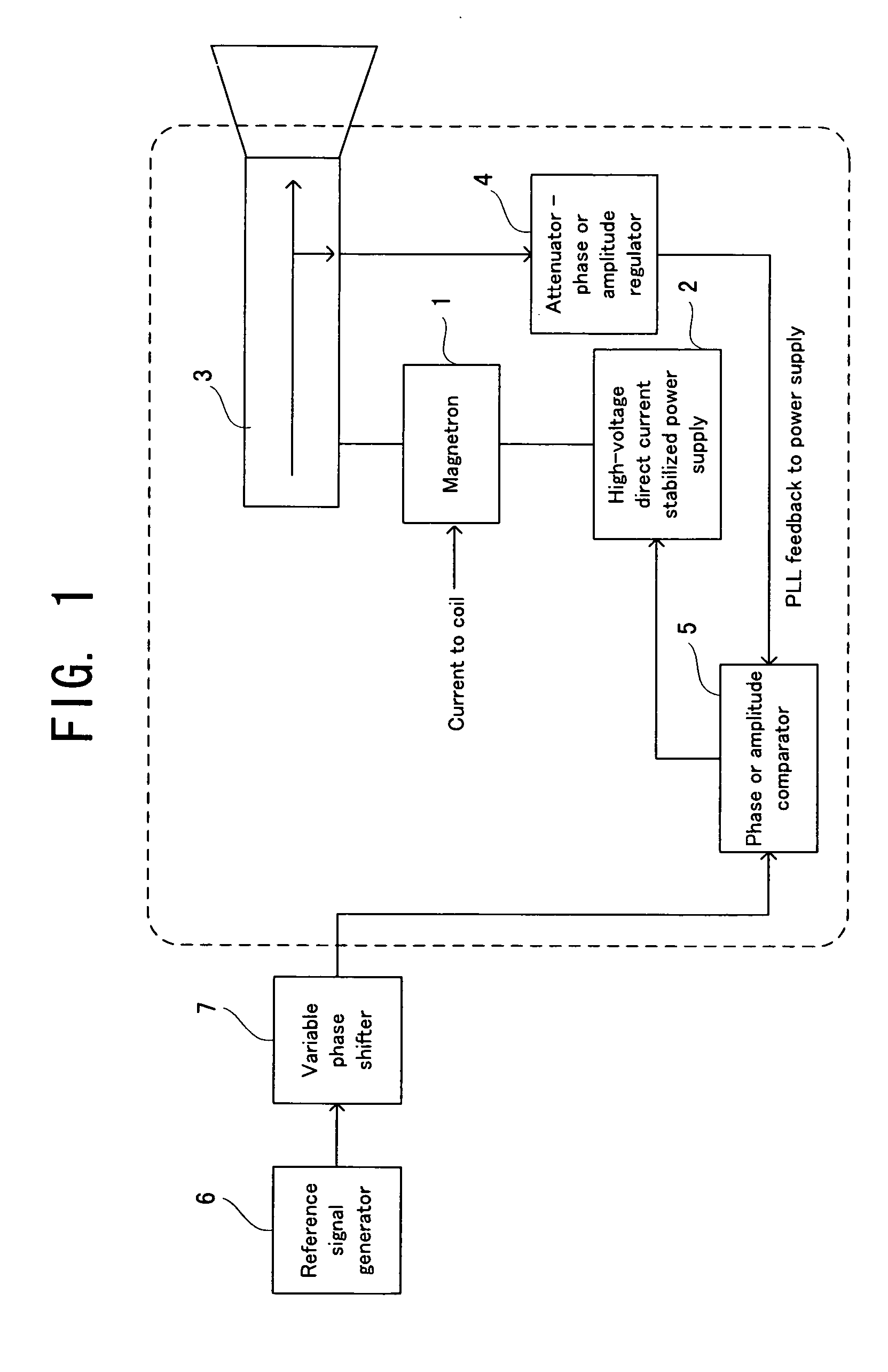
[0026]FIG. 1 is a diagram showing the microwave generating apparatus of the present invention. This microwave generating apparatus is provided with: a magnetron 1; a high-voltage direct current stabilized power supply 2; a directional coupler 3; an attenuator—phase or amplitude regulator (i.e., “attenuator” and “phase or amplitude regulator”) 4; a phase or amplitude comparator 5; a reference signal generator 6; and a variable phase shifter 7.
[0027] Between an anode (positive electrode) and a cathode (negative electrode) of the magnetron 1, which are not illustrated, a high-voltage direct current (hereinafter referred to as an “anode current”) is flown from the high-voltage direct current stabilized power supply 2. By this, the magnetron 1 is set in an oscillation state. A microwave radiated from the magnetron 1 is outputted to the exterior through the directional coupler 3. For example, it is transmitted to an electric supply system, such as a horn antenna.
[0028] The directional co...
second embodiment
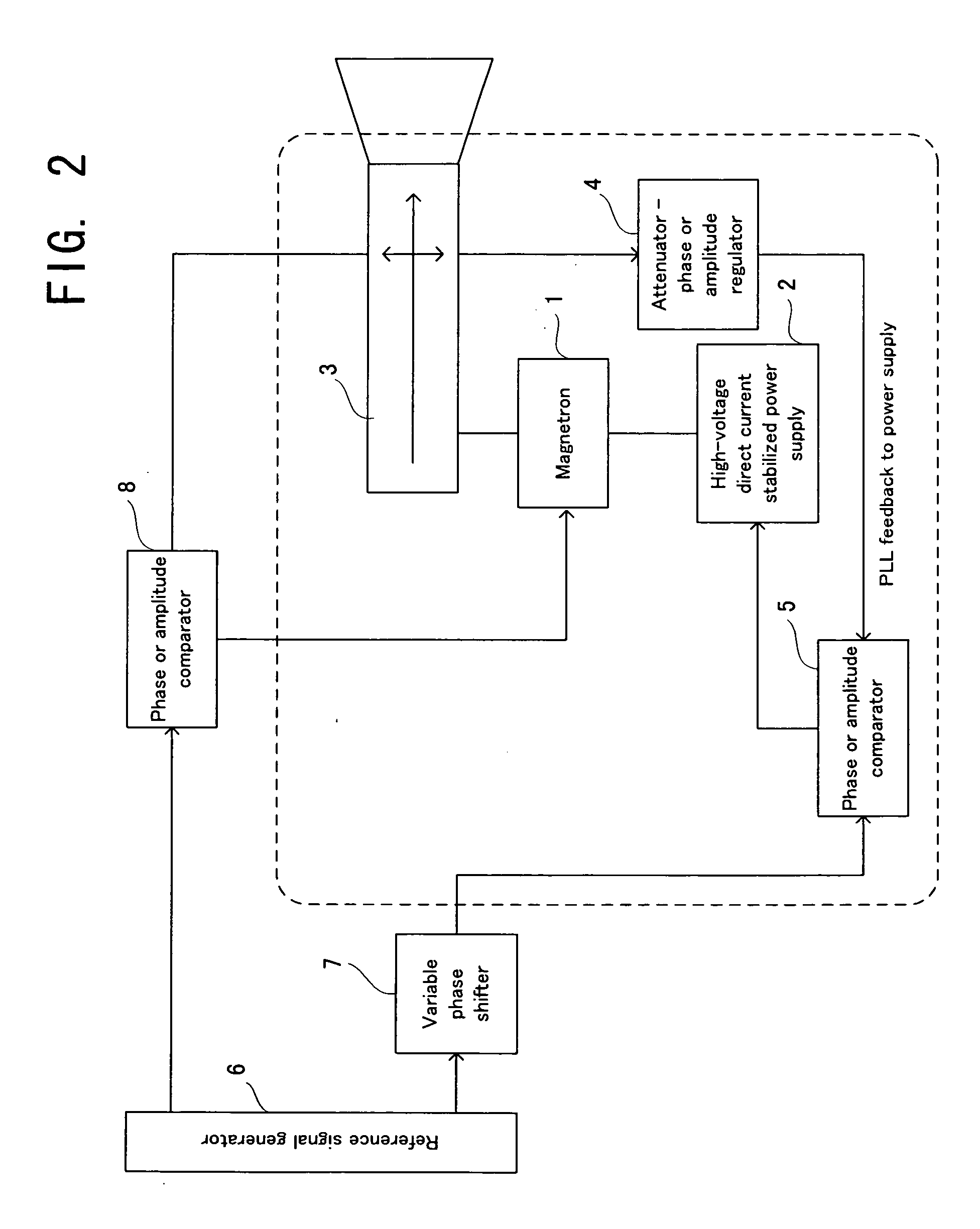
[0032]FIG. 2 is a diagram showing the microwave generating apparatus of the present invention. This microwave generating apparatus is provided with: the magnetron 1; the high-voltage direct current stabilized power supply 2; a directional coupler 3′; the attenuator—phase or amplitude regulator 4; the phase or amplitude comparator 5; the reference signal generator 6; the variable phase shifter 7; and a phase or amplitude comparator 8.
[0033] In this embodiment, the directional coupler 3′ also divergingly outputs one portion of the microwave output to the phase or amplitude comparator 8, in addition to the attenuator—phase or amplitude regulator 4. The reference signal is also supplied to the phase or amplitude comparator 8. The phase or amplitude comparator 8 compares the microwave with the reference signal, with regard to intensity, and actively changes the current of a not-illustrated coil such that the intensity of the microwave matches that of the reference signal, in accordance w...
third embodiment
[0034]FIG. 3 is a diagram showing the microwave generating apparatus of the present invention. This microwave generating apparatus is provided with: the magnetron 1; the high-voltage direct current stabilized power supply 2; the directional coupler 3; the attenuator—phase or amplitude regulator 4; the phase or amplitude comparator 5; the reference signal generator 6; the variable phase shifter 7; a distributor 9; and a circulator 10.
[0035] In this embodiment, the reference signal is supplied to the distributor 9 through the variable phase shifter 7. The distributor 9 distributes the inputted reference signal into two systems, such that the reference signal in one system is supplied to the circulator 10 and the reference signal in the other system is supplied to the phase or amplitude comparator 5.
[0036] In the circulator 10, the reference signal supplied from the distributor 9 is inputted from a first terminal, and the inputted reference signal is outputted from a second terminal, ...
PUM
 Abstract
Description
Claims
Application Information