Shared receiver and transmitter filter

Inactive Publication Date: 2007-02-22
MEDIATEK INC
View PDF7 Cites 17 Cited by
  • Summary
  • Abstract
  • Description
  • Claims
  • Application Information

AI Technical Summary

Benefits of technology

[0011] In accordance with another aspect of the present invention, the calibration circuit selects the second selectable capacitor based upon an offset value of the first selectable capacitor. Since calibration performed with the reference capacitor compensates for a

Problems solved by technology

Unfortunately, the goal of having less distortion conflicts with the design goal of providing more rejection of noise and interference.
However, separate transmi

Method used


Image

  • Shared receiver and transmitter filter
  • Shared receiver and transmitter filter
  • Shared receiver and transmitter filter

Examples


Embodiment Construction

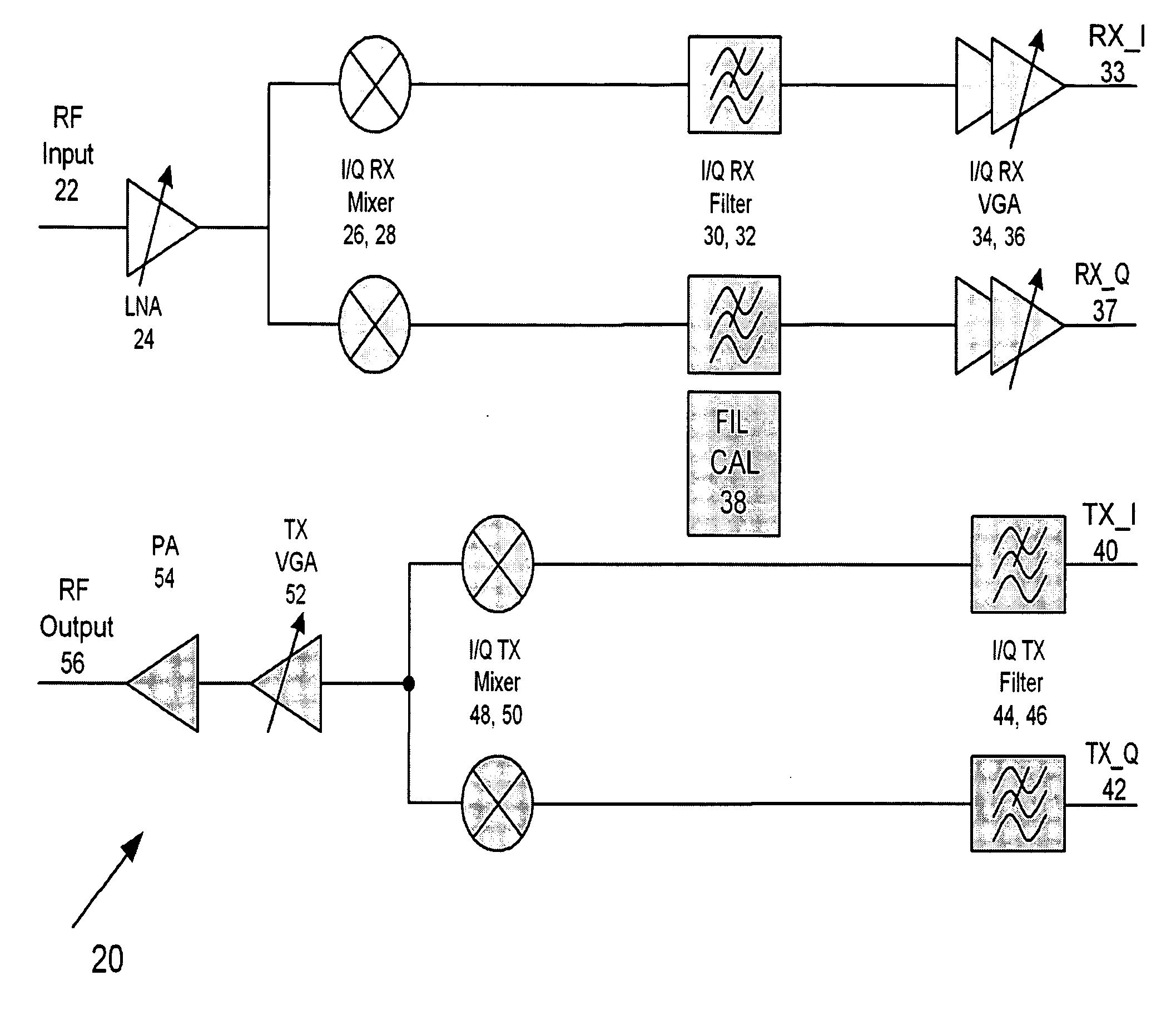
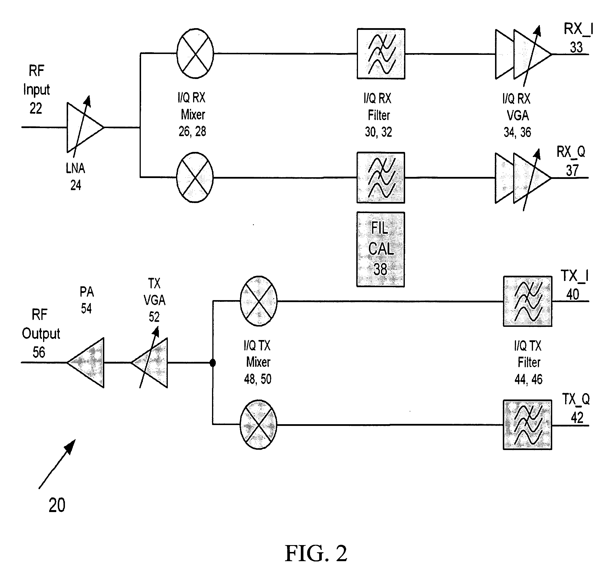
[0024] As disclosed below, the present invention provides methods and apparatuses for a shared filter. In general, this invention provides a single filter serving for both transmit and receive with two different calibrated filter bandwidths. According to an embodiment of the present invention, a shared filter serving a receive or transmit function with a first calibrated filter bandwidth that is different from serving a transmit or receive function with a second calibrated bandwidth is used for time division multiple access (TDMA) communication systems. Typical examples of a TDMA communication system are wireless local area network (WLAN) such as IEEE 802.11 standard. In these kinds of systems, since receive and transmit functions do not occur at the same time, sharing one filter which has a different bandwidth for receiving and transmitting can be accomplished.

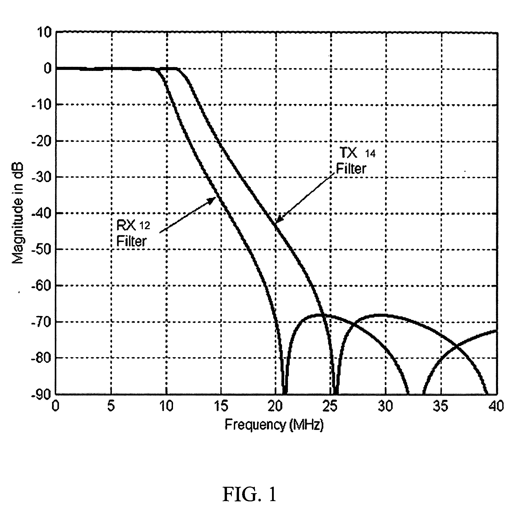
[0025]FIG. 1 is a graph showing different frequency responses for a receive filter and a transmit filter. Both receive and...


PUM


Abstract

The present invention provides methods and apparatuses for a shared filter transceiving system. A shared filter transceiving system having a capacitor bank to adjust the time constant of the shared filter comprises a first input configured to receive a first signal. The capacitor bank is coupled to the first input having a plurality of selectable capacitors including a reference capacitor. A second input is coupled to the capacitor bank configured to receive a second signal. A configurable switch is coupled to the capacitor bank configured to couple a first selectable capacitor with the reference capacitor when the first input is active and couple a second selectable capacitor with the second reference capacitor when the second input is active. The second selectable capacitor is a predetermined offset value of the first selectable capacitor.

Description

FIELD [0001] The present invention relates to filters for communication systems and, more particularly, to methods and apparatuses for a shared receiver and transmitter filter system. BACKGROUND [0002] Filter design plays a very important role in communication systems. Ideally, a receiver channel filter passes the desired signal with minimum signal distortion, maximize signal to noise ratio, rejects out of band interferences, and limits the noise bandwidth to a satisfactory level. Unfortunately, the goal of having less distortion conflicts with the design goal of providing more rejection of noise and interference. Therefore, the receiver filter is often designed with a number of trade-offs. [0003] On the other hand, a transmitter filter is designed to limit or shape the transmitted signal bandwidth within a particular transmitted spectrum in order to satisfy regulations and / or standards. Since a transmitted signal for digital communications is typically generated by digital to analo...

Claims


Application Information

Patent Timeline
IPC IPC(8): H03K5/00
CPCH03H7/0153H03H2210/043H03J5/244H03J2200/10
Inventor FAN, YIPINGWANG, CHANG-YULI, HONGYUCHAO, CHIEH-YUAN
Owner MEDIATEK INC
Why Eureka
Try Eureka