Rendering translucent layers in a display system

a display system and translucent technology, applied in the field of computer-implemented display systems, can solve the problems of poor performance, more complex processing, and slow writing date to frame buffers, so as to improve graphics system performance, avoid unnecessary write operations, and reduce flickering effects

Inactive Publication Date: 2007-02-22
APPLE INC
View PDF16 Cites 41 Cited by
  • Summary
  • Abstract
  • Description
  • Claims
  • Application Information

AI Technical Summary

Benefits of technology

[0013] In accordance with the present invention, there is provided a rendering system and method that facilitates efficient compositing of translucent and complex-shaped overlapping layers. An alpha channel is provided for each layer, in order to allow transparency characteristics to be specified on a pixel-by-pixel basis within the layer. Rendering is performed in front-to-back sequence, so that the invention is able to avoid unnecessary computations on layer portions that do not contribute to the final image. In addition, in one embodiment, compositing is made more efficient by first subdividing the image area into rectangles, wherein the set of overlapping layers (and their ordering) for all points within a given rectangle is constant. Compositing operations can then be performed on each rectangle separately, so as to avoid complex and time-consuming bounds-checking operations inside the innermost loop of the processing operation.
[0015] The present invention thus avoids reading pixel data that corresponds to pixels that do not contribute to the final image. This economy in image processing results in improved performance of the graphics system. In addition, if the destination bitmap is the frame buffer, flickering effects are reduced because each pixel in the destination bitmap is written at most once. The present invention also enables easy implementation of visual effects such as fading in or fading out of windows, as well as shadows, glow effects, and the like.
[0016] Additional performance enhancement is achieved, in one embodiment, by tagging the topmost layer that has changed since the last update. If the front-to-back compositing operation stops before reaching the tagged layer, it is not necessary to write the result to the output bitmap (the frame buffer), since the output bitmap already contains the same data, from the last update. The present invention can thus avoid unnecessary write operations in such a situation, and thereby improve system performance, particularly when output is being written to the frame buffer.
[0017] In one embodiment, additional optimization is achieved by initially subdividing the destination bitmap into a number of tiles, each tile containing the same stack of layers to be rendered. By performing such subdivision, the present invention is able to make determinations as to which layers may contribute to the final image on a tile-by-tile basis rather than on a pixel-by-pixel basis. This simplifies the bounds-checking process, and minimizes the number of calculations that need be made in the innermost loop of the process, thus improving overall performance.
[0018] The present invention can be implemented, for example, in a windowing system to provide efficient rendering of overlapping translucent windows in an improved graphical user interface.

Problems solved by technology

Rendering and displaying an image having two or more overlapping layers presents certain problems, particularly in determining how to render that portion of the image where the layers overlap.
However, when overlapping layers are translucent, more complex processing may be called for, as some interaction among picture elements (pixels) in each overlapping layer may take place.
Generally, however, such techniques are directed toward compositing only two layers at a time.
If the image is constructed in the frame buffer, on-screen flicker may result as the system writes to the frame buffer several times in succession.
In addition, step-by-step generation of the final image may result in poor performance due to the large number of arithmetic operations that must be performed.
Writing date to a frame buffer is particularly slow on many computers; therefore, conventional systems which write several layers to the frame buffer in succession face a particularly severe performance penalty.
Finally, such a technique often results in unnecessary generation of some portions of image elements that may later be obscured by other image elements.
Such techniques often result in additional processing time for areas of the windows that may have no effect on the final image.

Method used


Image

  • Rendering translucent layers in a display system
  • Rendering translucent layers in a display system
  • Rendering translucent layers in a display system

Examples


Embodiment Construction

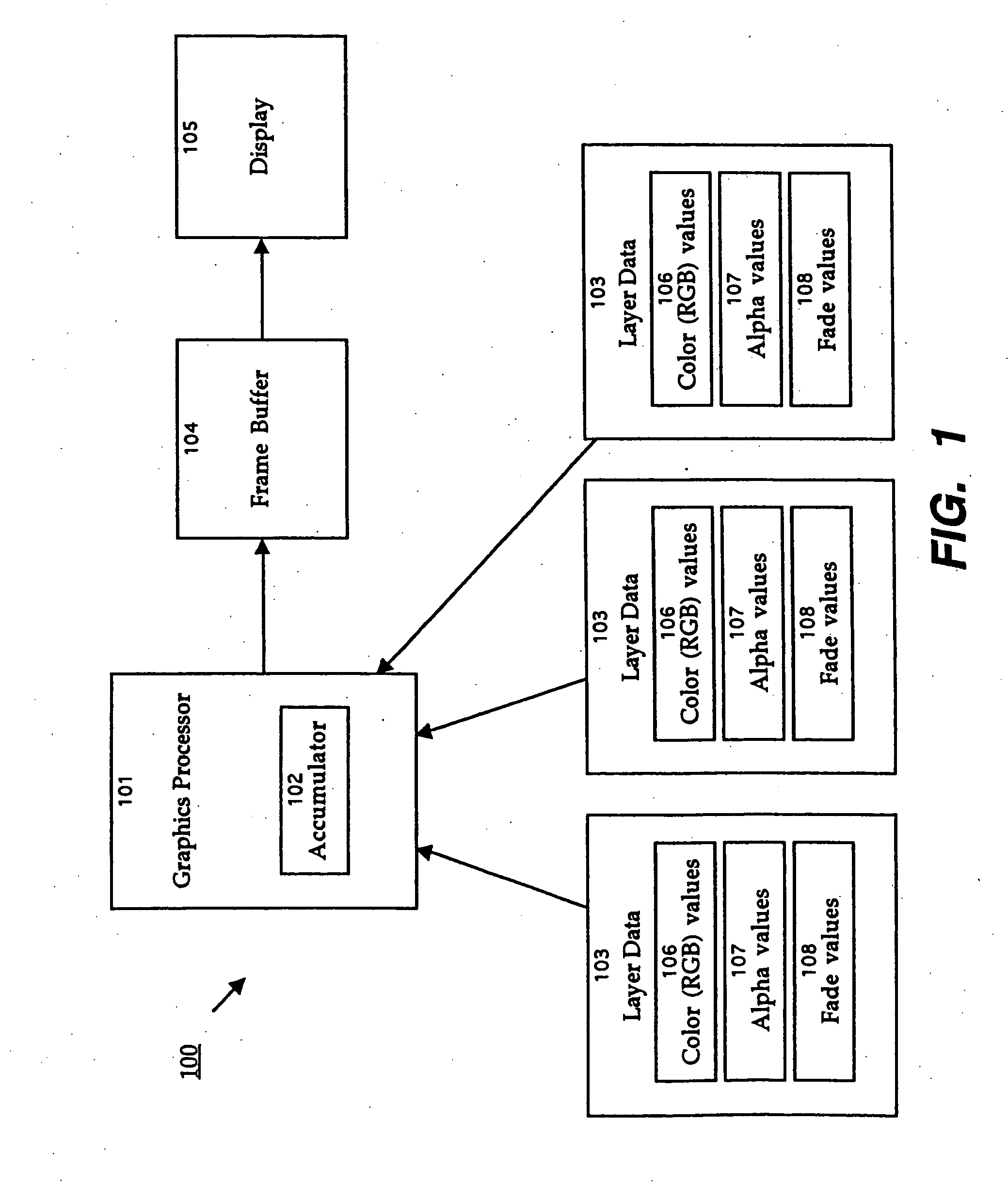
[0028] Referring now to FIG. 1, there is shown a block diagram of the overall architecture of one embodiment of the present invention. In this embodiment, system 100 is implemented on a conventional personal computer having a central processing unit and / or graphics processor 101 and a display 105 such as a cathode ray tube (CRT) or liquid crystal display (LCD) device. The steps of the present invention may be stored as software in an operating system or application software for execution by processor 101 in the computer, as is known in the art. For example, system 100 may be implemented on a Macintosh® computer, from Apple Corporation, running the MacOS operating system, and the software may form part of a Window Server module within the operating system.

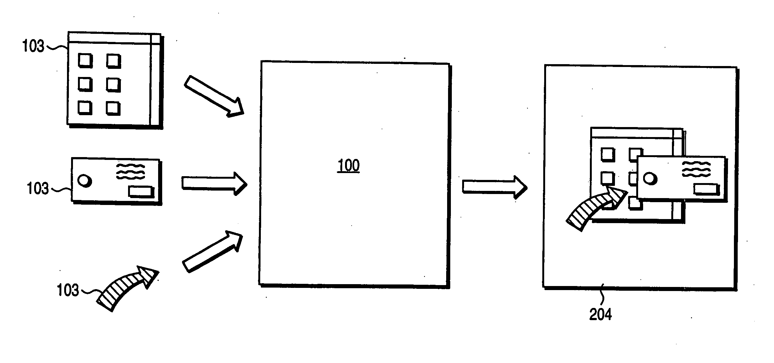
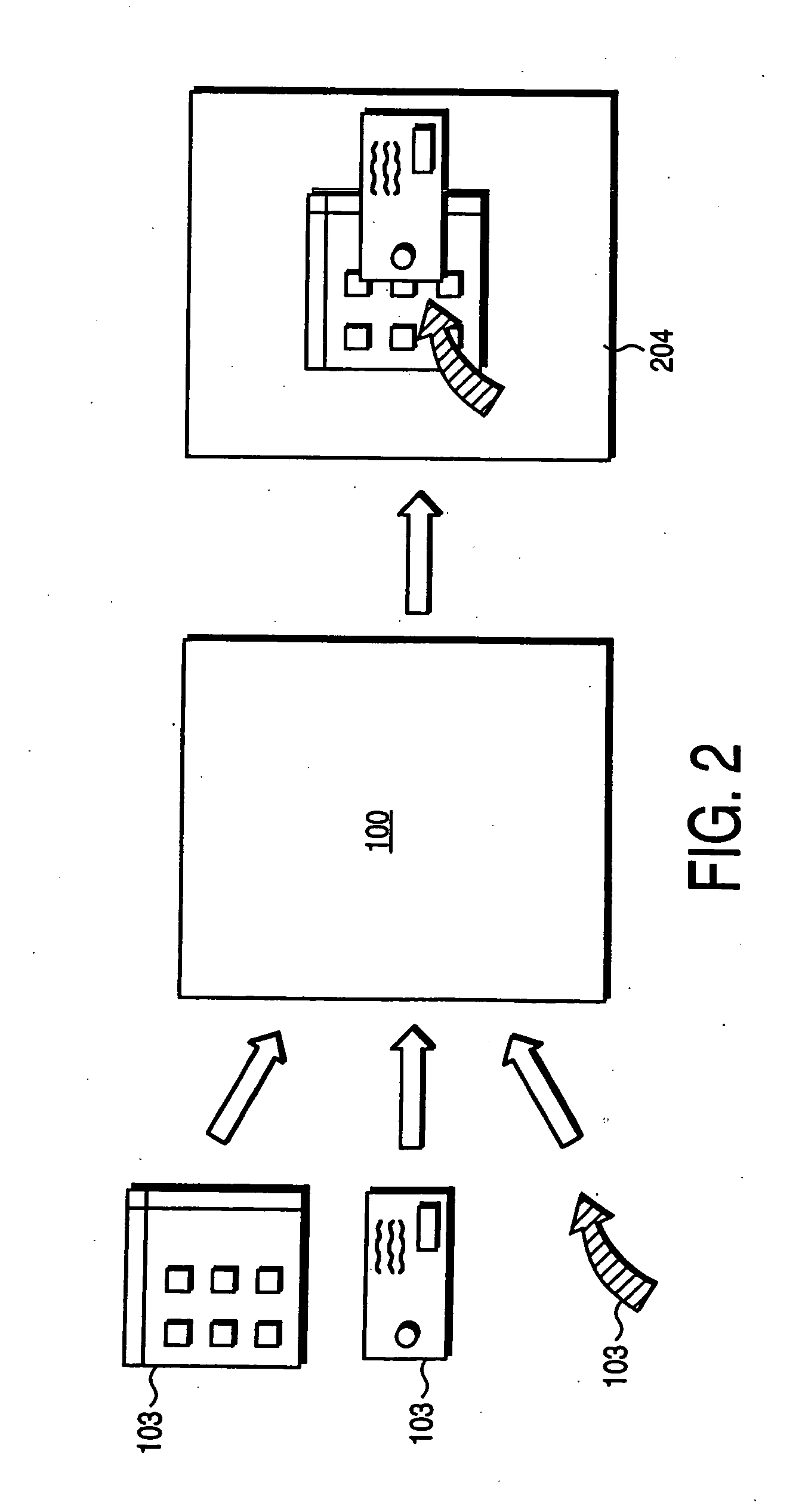
[0029] Layer data 103 represent source images to be composited for display on display 105. For example, layer 103 may include bitmap representations of windows, graphical user interface (GUI) elements, photographs, drawings, animat...


PUM


Abstract

A system and method of rendering overlapping layers in a computer display, such as a windowing system, employs front-to-back assembly of the displayed image. An arbitrary number of overlapping elements, such as windows, can be presented, without requiring temporary storage space or additional off-screen buffers. The front-to-back assembly technique minimizes the number of memory transfers performed in connection with rendering an image, and avoids unnecessary reading and processing of pixels that will not contribute to the final image. Special effects such as semi-transparency, shadows, and irregular shapes can be accommodated and processed in an efficient manner.

Description

CROSS REFERENCE TO RELATED APPLICATIONS [0001] This application is a continuation of U.S. patent application Ser. No. 10 / 017,674, filed on Dec. 14, 2001, which is a continuation of U.S. patent application Ser. No. 09 / 309,171, filed on May 10, 1999, now U.S. Pat. No. 6,369,830, the disclosure of which is hereby incorporated by reference.BACKGROUND OF THE INVENTION [0002] 1. Field of the Invention [0003] The present invention relates generally to computer-implemented display systems, and more particularly to a system and method of rendering translucent and complex-shaped overlapping layers in a display system. [0004] 2. Description of Background Art [0005] Many existing display systems are capable of compositing two or more display elements to generate a final image. In such systems, display elements often include overlapping layers, such as for example in a windowing system for a graphical user interface wherein on-screen elements, such as windows, may be moved around and placed on t...

Claims


Application Information

Patent Timeline
Patent Type & Authority Applications(United States)
IPC IPC(8): G09G5/00G06T3/00G06T15/40G09G5/377
CPCG06T15/40G09G5/026G09G5/14G09G5/393G09G2310/04G09G2340/125G06T11/40
Inventor BRUNNER, RALPH T.GRAFFAGNINO, PETER
Owner APPLE INC
Why Eureka
Try Eureka