Capillary tube flow cell

Inactive Publication Date: 2007-02-22
GL SCI
View PDF4 Cites 13 Cited by
  • Summary
  • Abstract
  • Description
  • Claims
  • Application Information

AI Technical Summary

Benefits of technology

[0026] The greatest advantage of the present invention described above is that the capillary tube and the ball lens are integrated as the capillary tube unit, and that this capillary tube unit is formed so as to be connectable to and separable from the sensor portion unit and the light inc

Problems solved by technology

However, because of the minimization of flow rate these capillary tubes have become increasingly small and clogging has become apt to occur.
However, the replacement work is very difficult and requires specialized knowledge and experience and in addition, it takes time to replace capillary tubes.
Therefore, general users cannot easily replace capillary tubes.
In particular, it takes time to adjust an optical system of a capillary tube, thereby making analysis operations difficult.
However, if the slit diameter is too small on this occasion, detection noise increases because the quanti

Method used


Image

  • Capillary tube flow cell
  • Capillary tube flow cell
  • Capillary tube flow cell

Examples


Example

Example 1

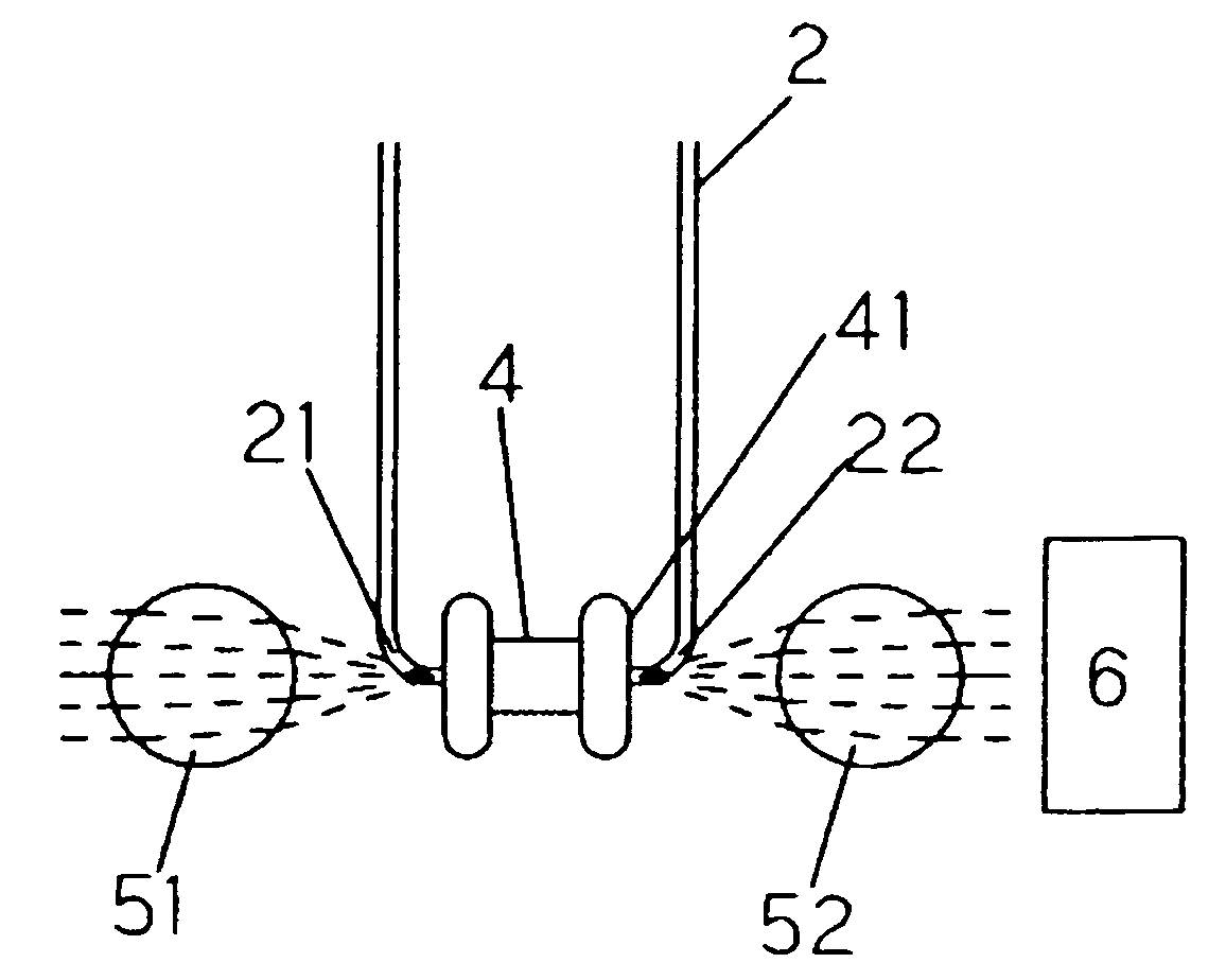
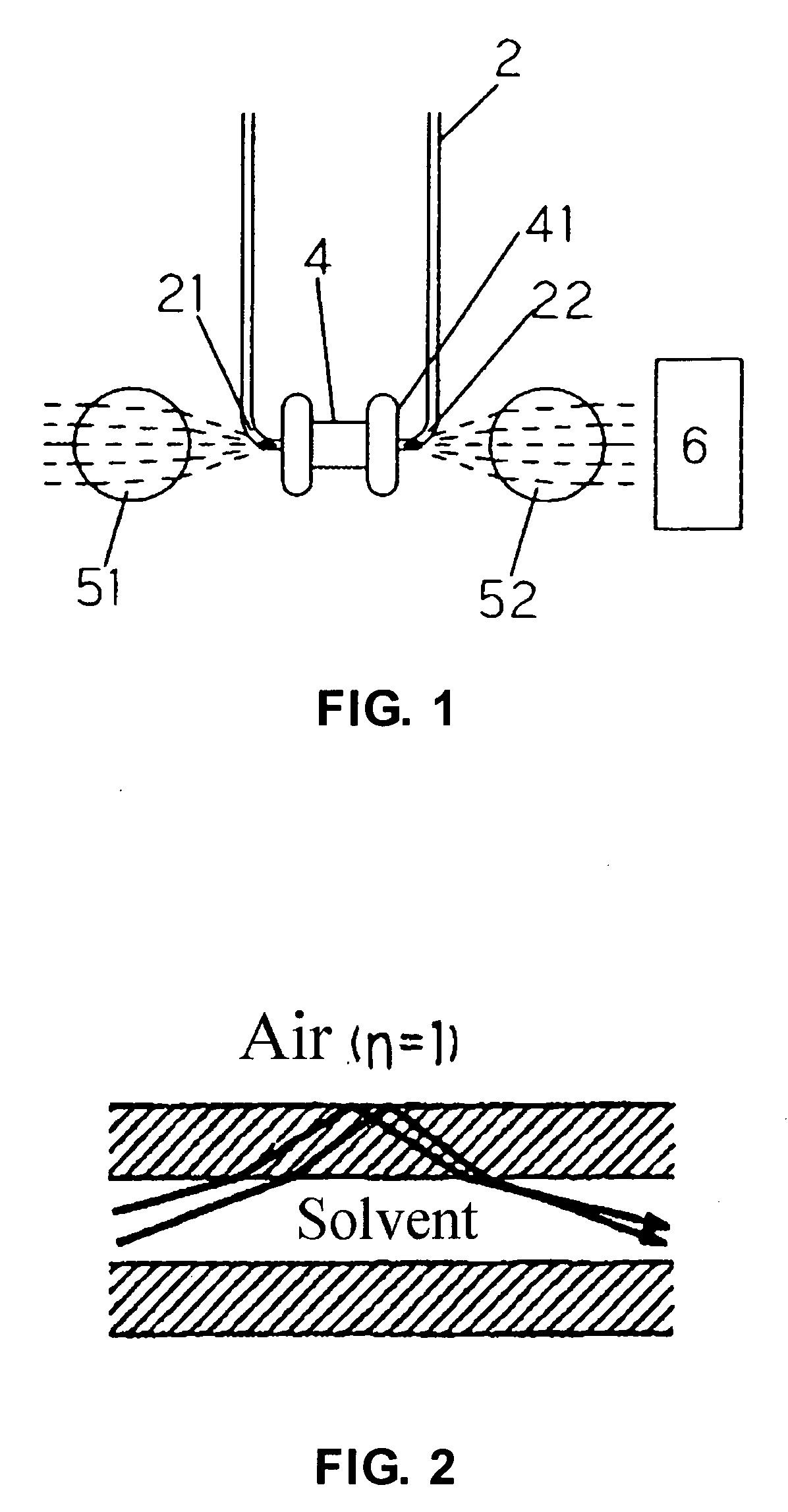
[0097] As the present invention the structure shown in FIG. 1 was used and as a prior art the structure shown in FIG. 14 was used as an optical system which causes light to become incident in a direction orthogonal to the capillary tube flow passage. A comparative experiment of absorbance was conducted under the following conditions.

Conditions

[0098] Wavelength: 254 nm

[0099] Mobile phase: MeCN / H2O=65:35

[0100] Flow rate: 5 μl / min

[0101] Standard sample for evaluation: Sample solution containing acetophenone, benzene, toluene and naphthalene in (MeCN / H2O=65:35)

[0102] Column: Inertsil® ODS-3 (0.3 mm i.d. ×15 cm)

[0103] Column temperature: Room temperature (23° C.)

[0104] As a result, the chromatogram shown in FIG. 15 was obtained.

[0105] The difference in absorbance is obvious, and the present invention exhibited higher sensitivity and peak height.

Example

Example 2

[0106] The structure of the present invention shown in FIG. 1 was used and the structure shown in FIG. 1 from which the ring 41 was removed was used. A response experiment of an absorbance detector was conducted under the following conditions.

Conditions

[0107] Response of detector: 0.1 sec and more

[0108] Wavelength: 254 nm

[0109] Mobile phase: MeCN / H2O=65:35

[0110] Flow rate: 5 μl / min

[0111] Column temperature: Room temperature (23° C.)

[0112] As a result, the chromatogram shown in FIG. 16 was obtained.

[0113] The difference in the base line noise is obvious, and in the present invention the noise is kept in a low level and stability is good.

[0114] The capillary tube flow cell of the present invention is useful in analyses at very low flow rates. This capillary tube flow cell is particularly useful in a flow cell in which a capillary tube is used, because any user can perform replacement of capillary tubes easily and in a short time without requiring any adjustment whe...


PUM


Abstract

Provided is a capillary tube flow cell used in analyses at very low flow rates and, particularly, in liquid chromatographic analyses. To ensure that high detection sensitivity and low noise can be realized, a flow cell which houses a liquid sample and exposes the liquid sample to radiant light for analysis purposes comprises a capillary tube which has a bent portion for incident light, a bent portion for emergent light and a linear passage of appropriate length formed between the bent portions, a passage portion of the capillary tube being inserted into a slit and the slit being provided with a light pass preventing portion.

Description

TECHNICAL FIELD [0001] The present invention relates to a capillary flow cell used in liquid chromatographic analyses and, in particular, in analyses at very low flow rates. BACKGROUND OF THE ART [0002] In analyses at very low flow rates, capillary tube flow cells have been frequently used because of their high detection sensitivity. [0003] For example, capillary tube flow cells are often used when mass spectrometers are used as detectors for the capillary electrophoretic process and liquid chromatograph and, in particular, when the detection of absorbance, fluorescence, etc. is performed. [0004] In a method described in the U.S. Pat. No. 5,057,216, a capillary tube is inserted into an optical passage, the capillary material is softened by heating both ends of the capillary tube, and the two ends are bent and formed in the shape of the letter Z or U, whereby a capillary flow cell is fabricated. [0005] And for this bending, the Japanese Patent Laid-Open No. 2002-267597 describes a be...

Claims


Application Information

Patent Timeline
IPC IPC(8): G01N21/05G01N27/62G01N21/17G01N27/447G01N30/74
CPCG01N21/05G01N30/74G01N2030/746G01N2021/0346
Inventor IWANO, TAKESHIYAMADA, TSUYOSHIZHOU, XIAOJING
Owner GL SCI
Why Eureka
Try Eureka