Switch mode power supply apparatus with multiple regulated outputs and a single feedback loop

a power supply apparatus and output technology, applied in the direction of electric variable regulation, process and machine control, instruments, etc., can solve the problems of high manufacturing cost of foil wound transformers, unsatisfactory smps 100/b> performance, and easy reduction of link current, so as to reduce manufacturing cost and complexity of the apparatus, and be potentially robust

Inactive Publication Date: 2007-02-22
KONINKLIJKE PHILIPS ELECTRONICS NV
View PDF4 Cites 6 Cited by
  • Summary
  • Abstract
  • Description
  • Claims
  • Application Information

AI Technical Summary

Benefits of technology

[0024] Preferably, the subsidiary rectifying means is devoid of active regulation components. Such an arrangement is capable of reducing manufacturing cost and complexity of the apparatus.
[0025] Preferably, the subsidiary rectifying means comprise an inductor, and a diode. Such components are relatively straightforward to procure from multiple sources, are potentially robust and are potentially inexpensive. The inductor is preferably not magnetically coupled to the inductive means.

Problems solved by technology

Moreover, the additional winding is connected such that a linking current is capable of flowing therethrough from the higher-voltage output to the lower-voltage output when the lower-voltage circuit is lightly loaded; the linking current is susceptible to decreasing as loading on the lower-voltage output increases.
Whereas operation for the load LD1 drawing in a range of 2 to 8 Amps and the load LD2 drawing in excess of 0.1 Amps is potentially acceptable in certain non-critical applications, the inventor has appreciated that performance of the SMPS 100 is unsatisfactory for many applications where circuit cost and complexity need to be reduced as much as possible and yet high quality regulation is required.
However, such foil wound transformers are expensive to manufacture and require specialist manufacturing skills in comparison to conventional winding techniques employed for enamelled copper wire.
Often such foil-wound magnetic components are expensive single-sourced items.
Conventional windings, for example enamelled copper wire windings, used in the transformer TR2 result in a degraded SMPS performance in comparison to that presented in FIG. 3.
However, such special transformer implementations are only capable in practice of reducing cross-regulation errors in the SMPS 100 to a range of 5 to 10% for moderate load current changes.
Such performance in many technical applications is not satisfactory.
As described in the foregoing, more precise regulation of the second secondary output V2 is feasible using active electronic devices, for example by including linear and / or switch mode regulator devices between the capacitor C2 and the load LD2, but is prohibitively expensive and / or too complex a solution and / or insufficiently power efficient for many practical applications where SMPS are required.

Method used


Image

  • Switch mode power supply apparatus with multiple regulated outputs and a single feedback loop
  • Switch mode power supply apparatus with multiple regulated outputs and a single feedback loop
  • Switch mode power supply apparatus with multiple regulated outputs and a single feedback loop

Examples


Embodiment Construction

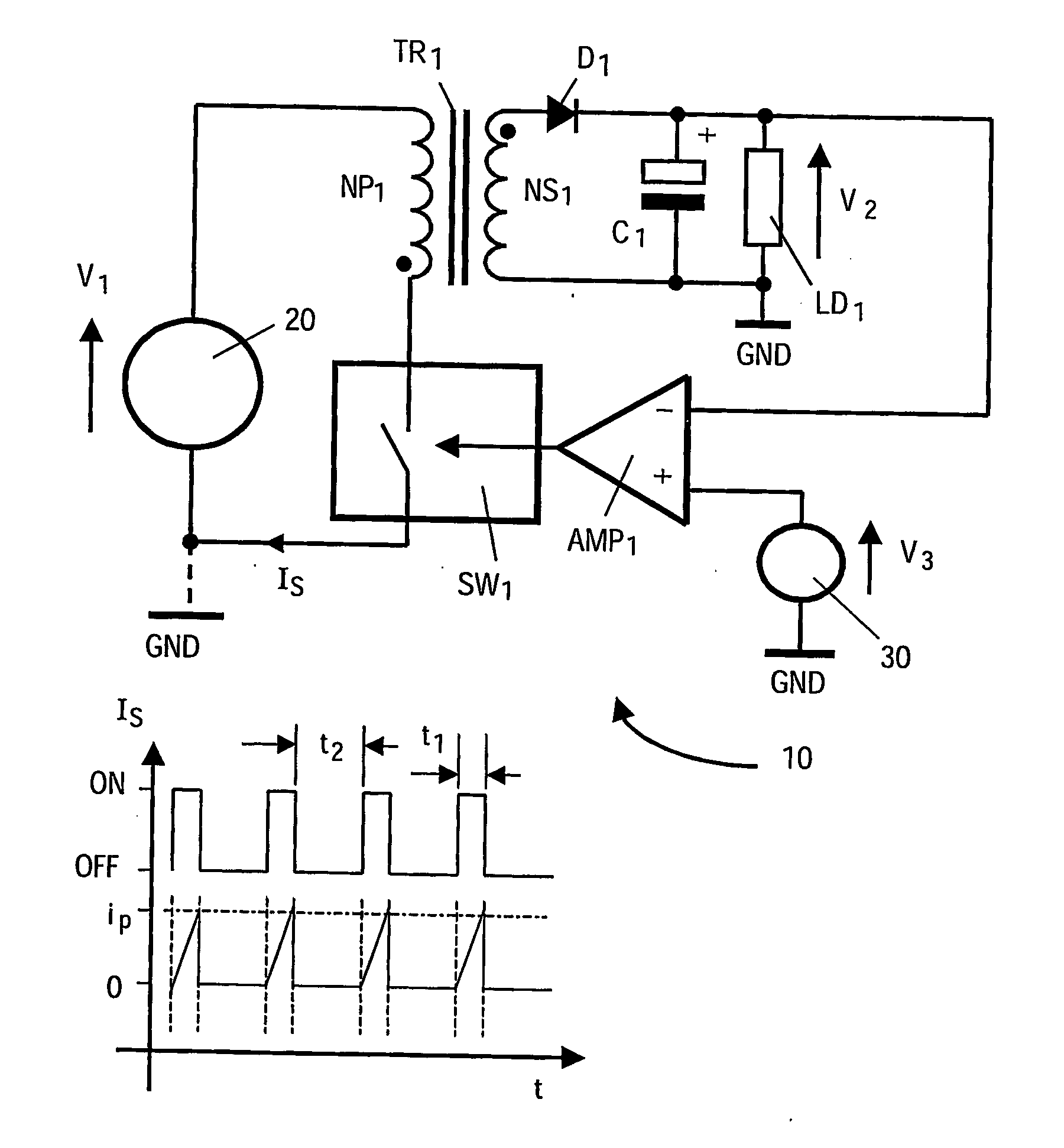
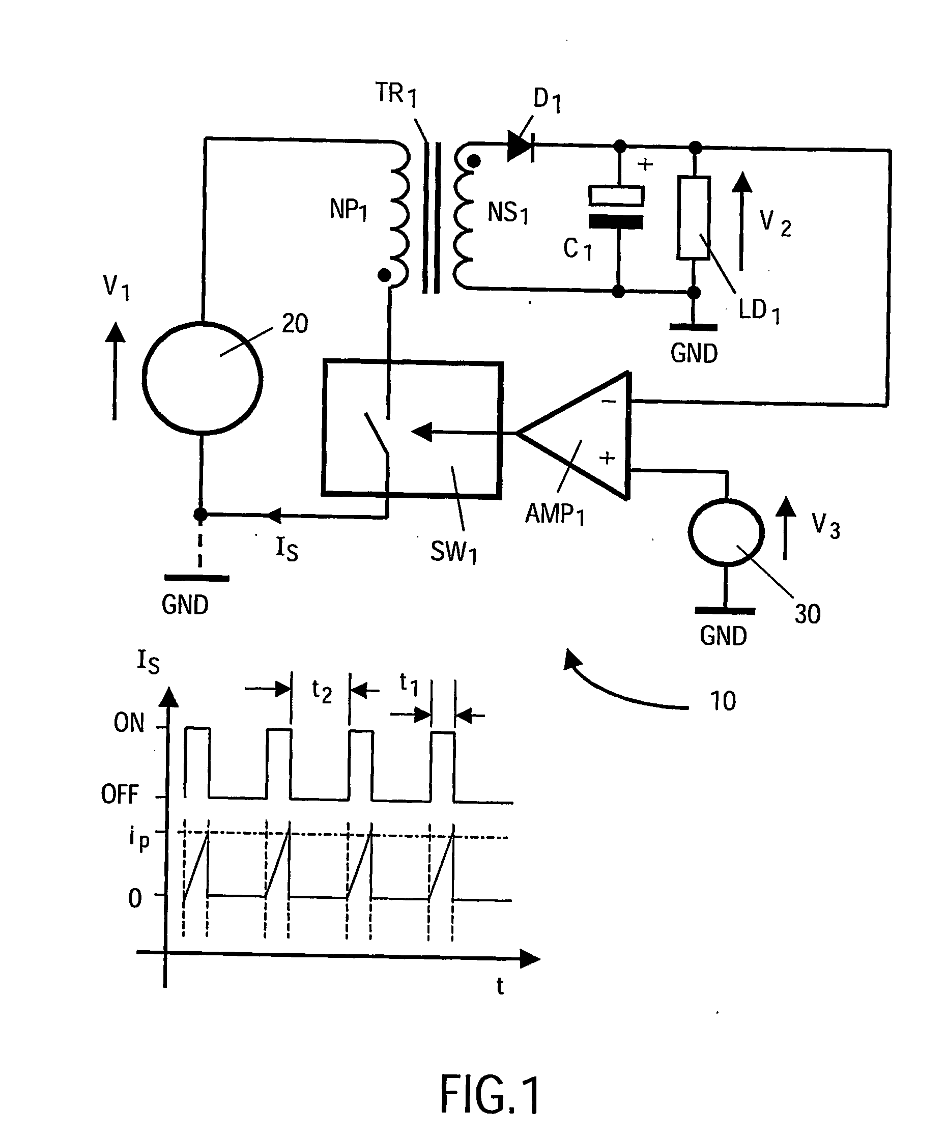
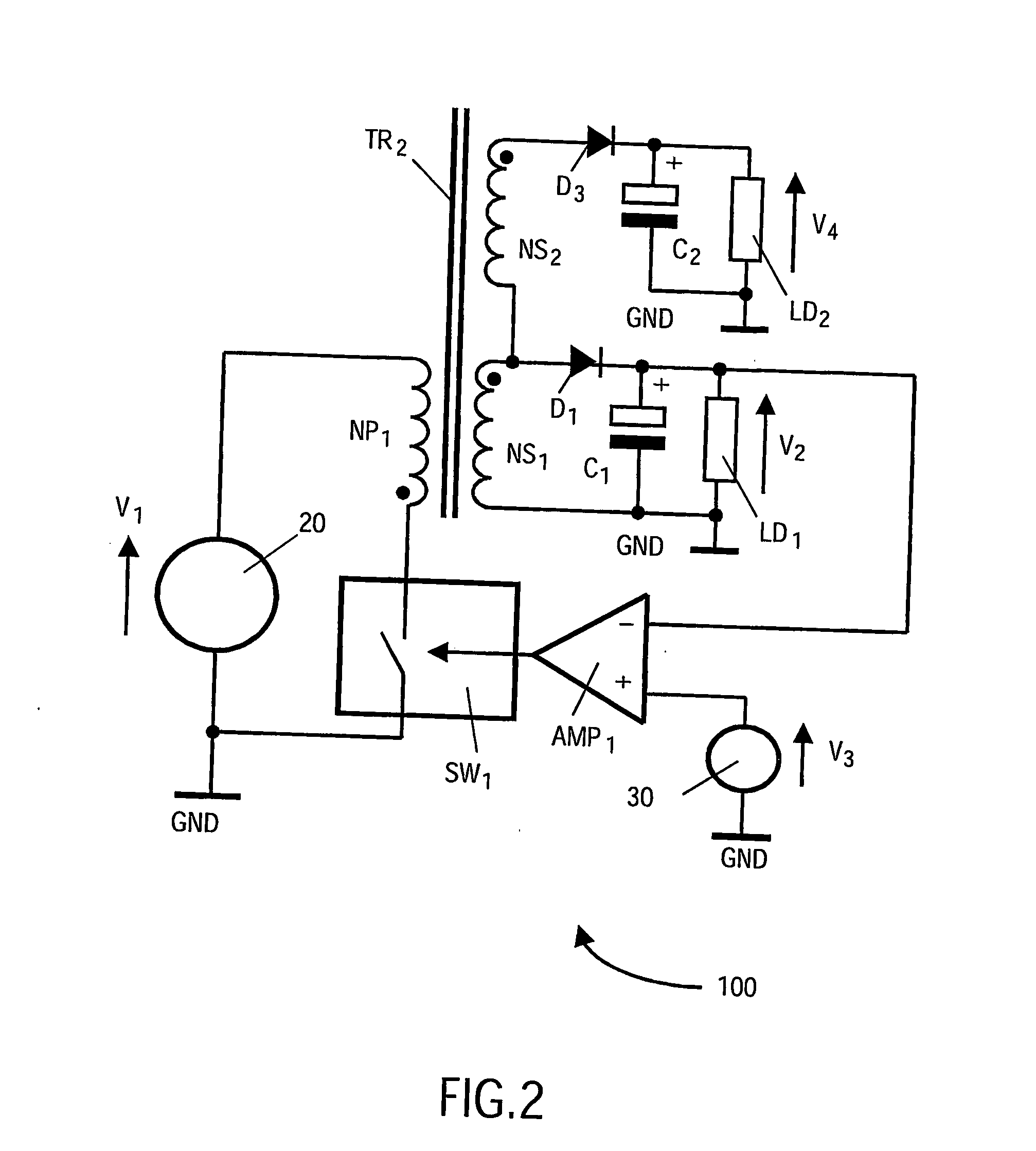
[0049] As described in the foregoing, the inventor has appreciated that an aforementioned contemporary flyback-mode switch mode power supply apparatus (SMPS) 100 illustrated in FIG. 2 provides an unsatisfactory quality of regulation at its additional output designated by V4; such unsatisfactory regulation is illustrated graphically in FIG. 3. Whereas the inventor has appreciated that the SMPS 100 is a conventional logical development from an aforementioned SMPS 10 illustrated in FIG. 1, the inventor has devised an alternative first flyback-type converter switch mode power supply apparatus (SMPS) according to the invention, the SMPS indicated generally by 200 in FIG. 4.

[0050] The SMPS 200 includes an aforementioned transformer TR1 as employed in the contemporary SMPS 10 together with its associated switching device SW1, its feedback control amplifier AMP1 and its voltage reference 30. An aforementioned primary winding NP1 of the transformer TR1 is connected at its first terminal to ...


PUM


Abstract

There is provided a switch mode power supply apparatus (200) for receiving an input supply voltage (V1) from an input supply source (20) and generating a corresponding main regulated output supply voltage (V2) and at least one subsidiary output supply voltage (V4). The apparatus (200) includes: (a) an inductive structure (TR1) having a terminal for providing a secondary output (NS 1); (b) a switching structure (SW1) coupled between the input supply source (20) and the inductive structure (TR1) for applying current to the inductive structure (TR,) in a switched manner, (c) a main rectifying structure (D, C1) for receiving the secondary output (NS2) and generating the main regulated output supply voltage (V2) therefrom; (d) a feedback structure (AMP,) for comparing the main regulated output supply voltage (V2) with at least one reference (30) to adjust operation of the switching structure (SW) so as to maintain the main output supply voltage (V2) in regulation; and (e) a subsidiary rectifying structure (210) comprising a voltage multiplier comprising a capacitor (C3) coupled to the terminal of the inductive structure (TR,) so as to receive signals therefrom which are subject to regulation by the feedback structure (AMP,) for generating the at least one subsidiary output voltage (V4).

Description

FIELD OF THE INVENTION [0001] The present invention relates to switch mode power supply apparatus (SMPS); in particular, but not exclusively, the invention relates to SMPS providing multiple regulated outputs whilst employing only a single feedback loop for providing such regulation. BACKGROUND TO THE INVENTION [0002] Switch mode power supply apparatus (SMPS) are widely known and employed in diverse applications such as computers, consumer electronic equipment, battery chargers to mention a few. When configured to receive an alternating current (a.c.) mains supply and deliver a regulated direct current (d.c.) output, the SMPS usually include a transformer whose primary winding is coupled via a switching arrangement to the rectified a.c. mains supply, a secondary winding coupled via a rectification arrangement to a charge storage arrangement across which the regulated d.c. output is generated, and a feedback arrangement coupled to the charge storage arrangement and to the switching a...

Claims


Application Information

Patent Timeline
Patent Type & Authority Applications(United States)
IPC IPC(8): H02H9/00H02M3/156H02M3/158H02M3/28H02M3/335
CPCH02M3/156H02M2001/009H02M1/009H02M3/28
Inventor MIERMANS, HUBERTUS CORNELIS
Owner KONINKLIJKE PHILIPS ELECTRONICS NV
Why Eureka
Try Eureka