
Optical head and optical information medium driving device

Inactive Publication Date: 2007-02-22
PANASONIC CORP
View PDF10 Cites 0 Cited by
  • Summary
  • Abstract
  • Description
  • Claims
  • Application Information

AI Technical Summary

Benefits of technology

[0026] According to this configuration, because the light-receiving element is directly laminated to the light flux separation element, misalignment of the light-receiving element with respect to the optical axis or the light flux separation element can be lessened. In addition, as a distance between the light flux separation element and the light-receiving element becomes shorter, relative misalignment with respect to each other is lessened, which can in turn lessen a quantity of light arriving at a position outside of the light-receiving surface of the light-receiving element. Hence, not only is it possible to increase a quantity of light incident on the light-receiving element, but it is also possible to lessen influences of the misalignment, which can in turn suppress variance in detection sensitivity. As a result, a quantity of light can be detected at high detection sensitivity, and a quantity of light of the light source can be therefore adjusted at a higher degree of accuracy.
[0039] When configured in this manner, because part of the light-receiving element is set inside the base of the objective lens moving mechanism with an adjustment margin, a projection area of the optical head can be smaller. This, therefore, contributes to a reduction of the disc recording and playback device in size.

Problems solved by technology

This poses a problem that accuracy of detection using the light-receiving element 36 cannot be ensured.

Method used


Image

  • Optical head and optical information medium driving device
  • Optical head and optical information medium driving device
  • Optical head and optical information medium driving device

Examples


Embodiment Construction

[0057] Hereinafter, one embodiment of the invention will be described with reference to the drawings.

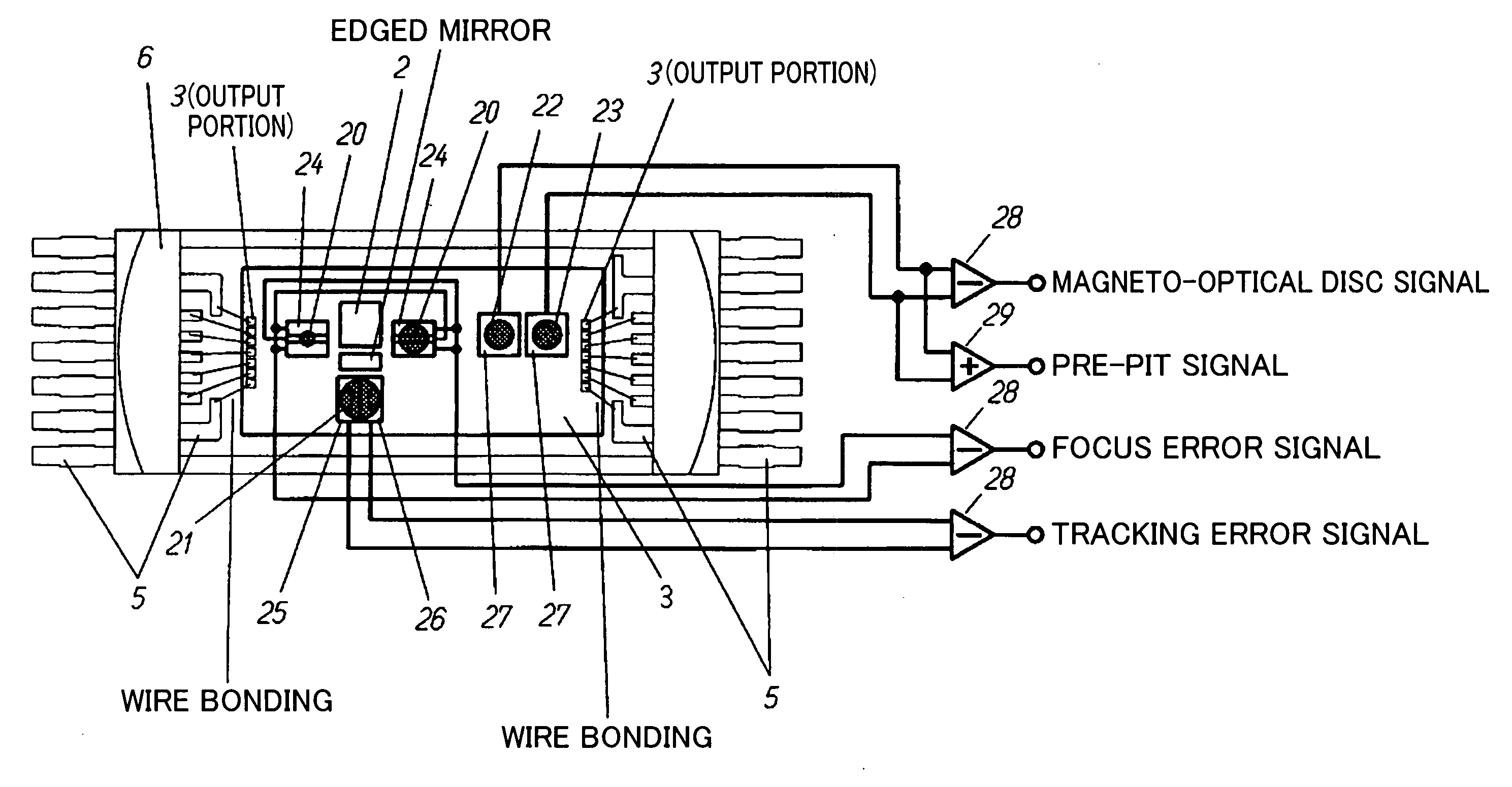
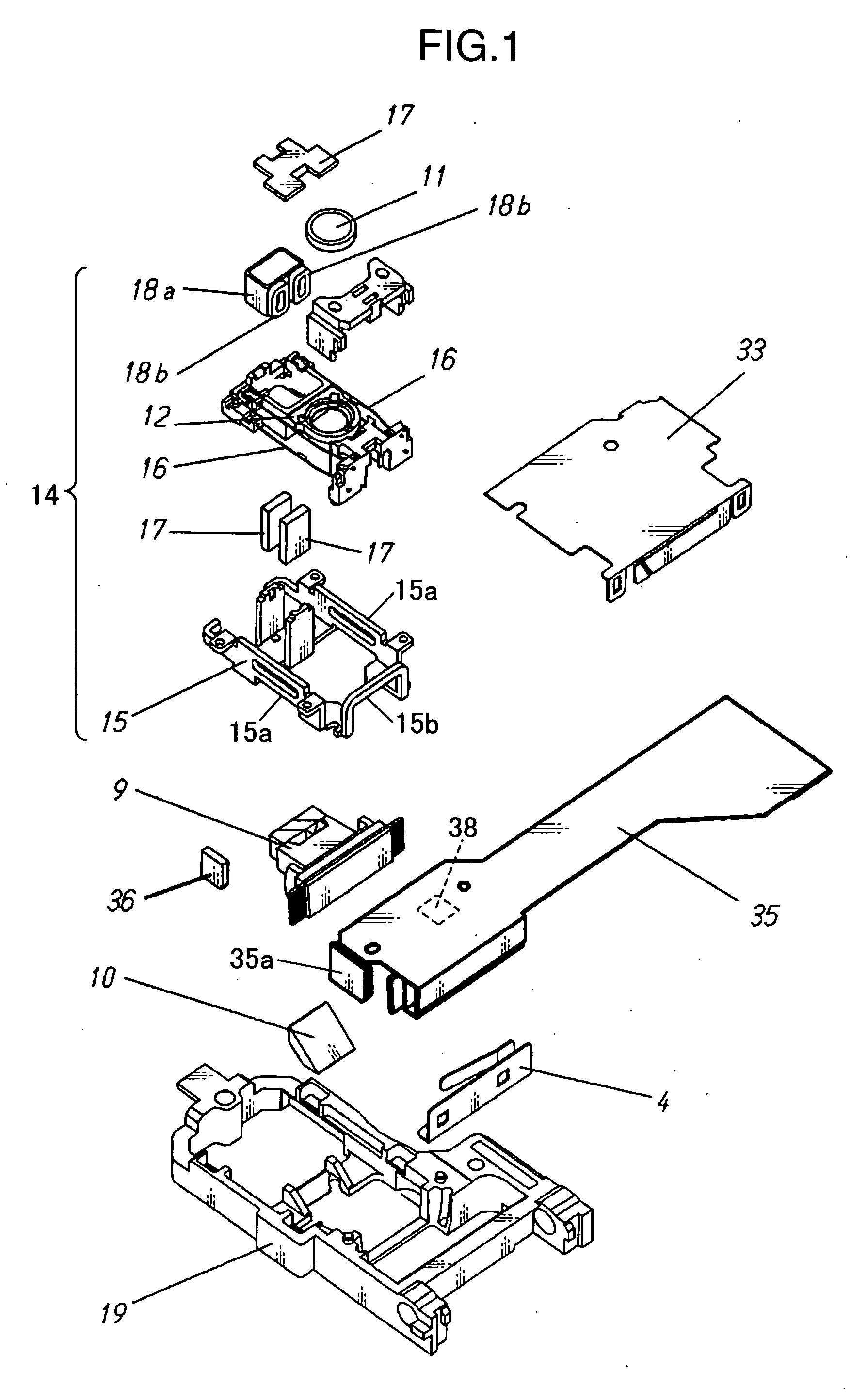
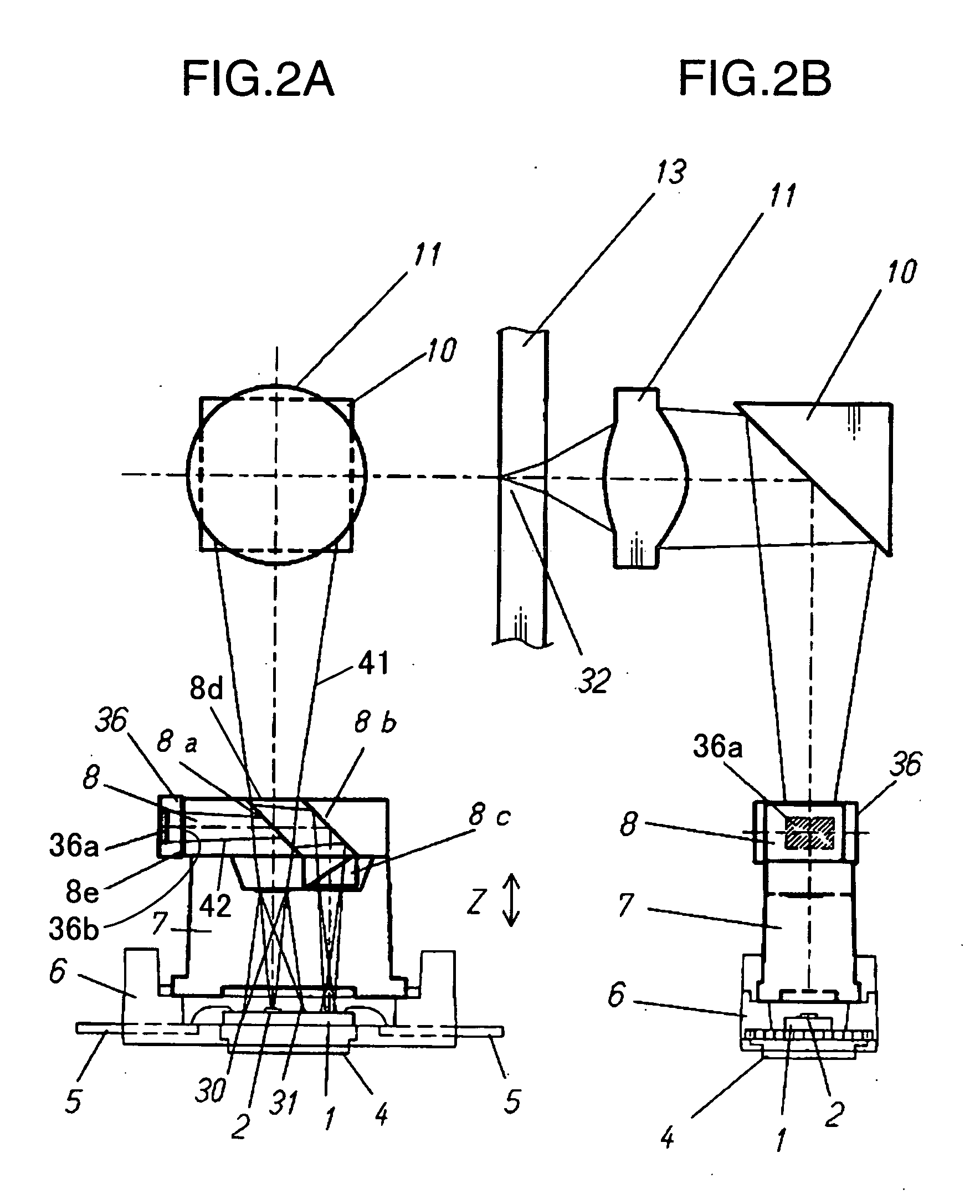
[0058]FIG. 1 is an exploded perspective view of an optical head according to one embodiment of the invention, and FIG. 2A and FIG. 2B are a schematic view showing an optical path in the optical head according to one embodiment of the invention. FIG. 3A and FIG. 3B show adjustment methods in the optical head according to one embodiment of the invention, and FIG. 4 is a schematic view of a photo-detector in the optical head according to one embodiment of the invention.

[0059] As are shown in FIG. 2A and FIG. 2B, a semiconductor laser 2 is fixed onto a silicon substrate 1, and a multi-splitting photo-detector 3 is formed on the silicon substrate 1 through the IC process. Also, a radiator plate 4 is held in a heat conduction state on the silicon substrate 1 via silver paste. Terminals 5 are wired to the multi-splitting photo-detector 3 through wire bonding or the like. These silicon sub...


PUM


Abstract

A semiconductor laser; a light flux separation element that separates a light flux emitted from the semiconductor laser for a first light flux and a second light flux to come out therefrom; an objective lens on which the first light flux coming out from the light flux separation element is incident to be collected on a optical information recording medium; a light-receiving element on which the second light flux coming out from the light flux separation element is incident; an arithmetic circuit that adjusts a quantity of light emitted from the light source in response to a quantity of light incident on the light-receiving element, are provided. A light exiting-surface of the light flux separation element from which the second light flux comes out is laminated to a light incident-surface of the light-receiving element on which the second light flux is incident via an adhesive layer. It is thus possible to adjust a quantity of light at a higher degree of accuracy and higher sensitivity while achieving a significant reduction of the optical head in size.

Description

BACKGROUND OF THE INVENTION [0001] 1. Field of the Invention [0002] The present invention relates to an optical head adapted to an optical information medium driving device adopting a system by which information is optically recorded and played back by projecting a light spot on a disc-shaped recording medium. [0003] 2. Description of the Related Art [0004] Recently, a disc recording and playback device has been expanding in application for a CD-ROM, a CD-R, an MD, a DVD-RAM, a Blu-ray disc, etc. from year to year, and the density, the performance, the quality, and added values are being enhanced; moreover, there has been a need for a significant reduction in size and cost. In particular, the demand for a portable disc recording and playback device with the recording capability tends to increase markedly, and there is a need to further reduce the device in size and thickness while improving the performance. [0005] There have been many reports, such as JP-A-2000-048374, on the techni...

Claims


Application Information

Patent Timeline
IPC IPC(8): G11B7/00G11B7/12G11B7/123G11B7/125G11B7/135G11B7/1356
CPCG11B7/1356G11B7/123
Inventor NAKATA, HIDEKITOMITA, HIRONORIOHTA, TAKESHI
Owner PANASONIC CORP
Learn More