RFID reader

Inactive Publication Date: 2007-02-22
LS IND SYETEMS CO LTD
View PDF9 Cites 22 Cited by
  • Summary
  • Abstract
  • Description
  • Claims
  • Application Information

AI Technical Summary

Benefits of technology

[0021] However, The demodulation using the In-phase and quadrature-phase requires that the same component be provided

Problems solved by technology

However, the digital data generated in the conventional RFID reader contain a lot of subharmonic components due to particular impulse characteristics, thus deteriorating frequency characteristics.
The deterioration in the frequency characteristic causes a problem of lowering performance of the RFID reader in a frequency environment where the channel bandwidth is a scarce and expensive resource.
The

Method used


Image

  • RFID reader
  • RFID reader
  • RFID reader

Examples


Embodiment Construction

[0045] Reference will now be made in detail to the preferred embodiments of the present invention, examples of which are illustrated in the accompanying drawings.

[0046] A receiving unit of an RFID reader according to embodiments of the present invention is now described which improves data reception in the RFID reader by detecting a level of the transmission signal using a root-mean square (RMS) method and demodulating the level of the transmission signal when demodulating a transmission signal transmitted from an RFID tag.

[0047] The RFID reader recognizes an RFID tag identification and data transmitted from the RFID tag when the RFID tag having the identification and the data is within a range of radio which an antenna of the RFID reader transmits. As a result, the RFID reader transmits the data to the host computer through a serial or ethernet connection.

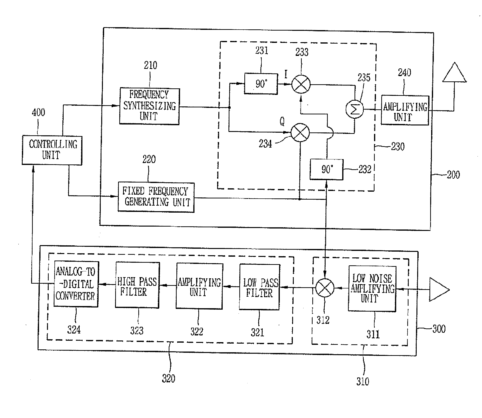
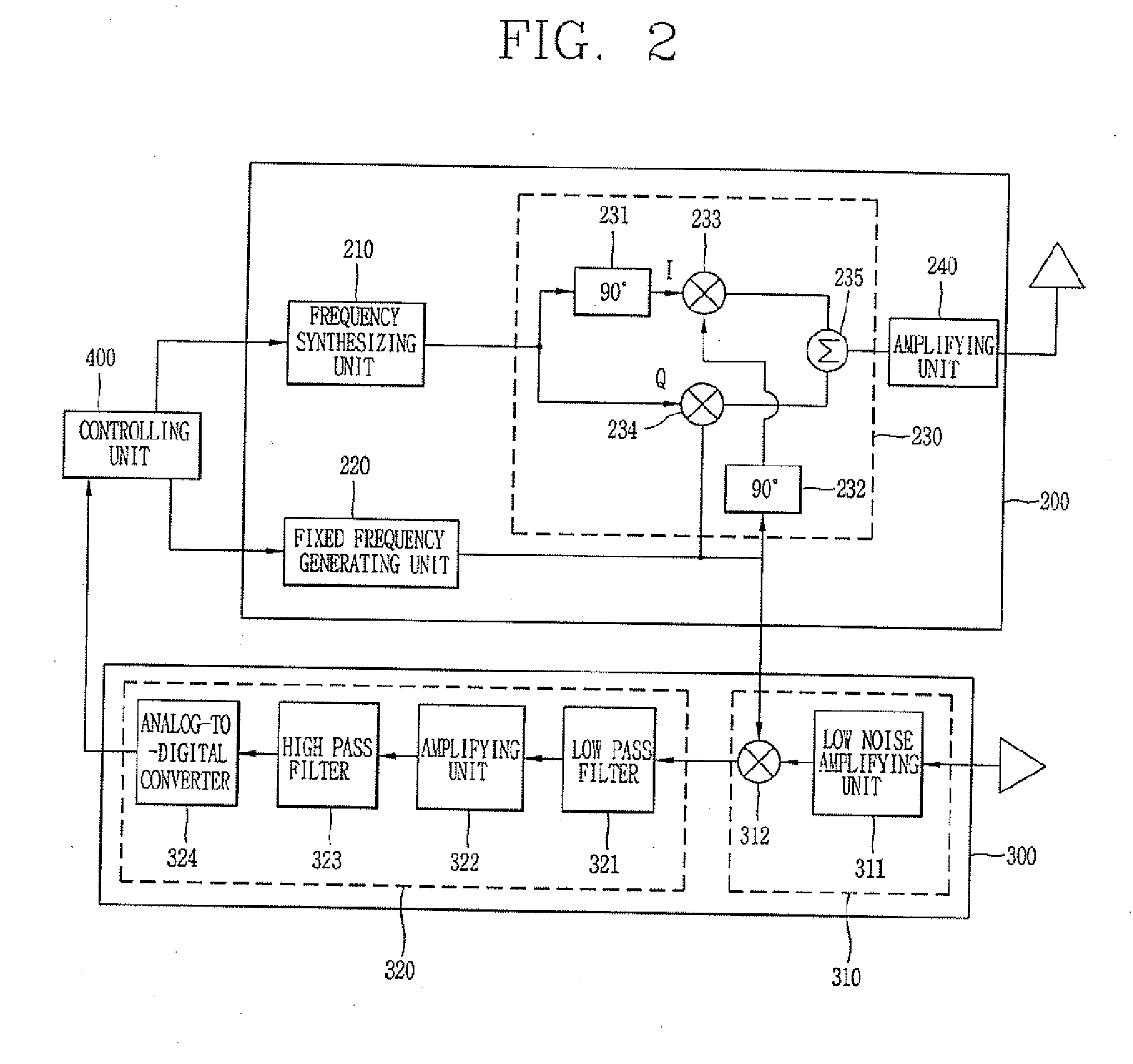
[0048]FIG. 2 is a block diagram showing a configuration of the RFID reader according to an embodiment of the present inventio...


PUM


Abstract

Provided are an RFID reader reading data from an RFID tag using a wireless connection over a specified frequency bandwidth, including a transmitting unit synthesizing sequentially and cumulatively frequency control signals generated every clock, mixing the synthesized specific frequency signal and a fixed frequency signal, and as a result outputting an RF signal.

Description

RELATED APPLICATION [0001] The present disclosure relates to subject matter contained in priority Korean Application No. 10-2005-0074920, filed on Aug. 16, 2005, which is herein expressly incorporated by reference in its entirety BACKGROUND OF THE INVENTION [0002] 1. Field of the Invention [0003] The present invention is related to a radio frequency identification(RFID) reader, and more particularly to a radio frequency identification capable of lowering power consumption and reducing a size by employing receiving and transmitting units of which structures are simplified. [0004] 2. Description of the Background Art [0005] In a typical radio frequency identification (RFID) system, objects are tagged with tiny radio tags (transponders) that carry certain data about the objects. The tags (transponders) transmit this data, through radio waves, to nearby readers, which collect and process the data accordingly. These transactions between RFID tags and the readers enable a multitude of app...

Claims


Application Information

Patent Timeline
IPC IPC(8): H04L27/06
CPCH04L25/03834H04L27/04H04L27/06G06K17/00H04L27/26
Inventor SEON, JONG-KUG
Owner LS IND SYETEMS CO LTD
Why Eureka
Try Eureka