Hydrodynamic closed loop turboset-selfbooster

a closed-loop, self-boostering technology, applied in the direction of liquid fuel engines, machines/engines, stators, etc., can solve the problems of large and costly fuel consumption, low total efficiency of about 40%, harm emissions, etc., to achieve substantial energy dissipation losses, high energy ratio, and harm emissions

Inactive Publication Date: 2007-02-22
LAZAR BERELI M
View PDF7 Cites 4 Cited by
  • Summary
  • Abstract
  • Description
  • Claims
  • Application Information

AI Technical Summary

Benefits of technology

[0015] It is another object of this proposal to provide clean natural technology without any pollutions and other harm emissions.
[0019] This accumulative and low-dissipating turbotechnology provides high energy ratio by self-boosting axial-flow propeller pump working in self-series; bispindle axial multistage wing-blade turbines; a closed-loop common tunnel having inside the high-potential operative liquid flow with its cyclical energy replenishing and smooth hydrodynamic interactions. The turbotechnology is natural, clean, has no pollutions, harm emissions and substantial energy dissipating losses.

Problems solved by technology

A common principal defect of most of them is their low about 40% total efficiency.
Their imperfect general technology leads to power wasting, large and costly fuel consumption, and non-prospective burning out their combustibles.
These conventional heat engines and some turbines are ineffective because of high energy dissipating.
They pollute the nature and carry huge costs to end users.
Some fragmentary elements of testing closed fluid dynamic tunnels could be regarded like a far prior art details but these tunnels had never even been considered as a possible base for redeveloping into power units despite their formal high energy ratio.

Method used


Image

  • Hydrodynamic closed loop turboset-selfbooster
  • Hydrodynamic closed loop turboset-selfbooster
  • Hydrodynamic closed loop turboset-selfbooster

Examples


Embodiment Construction

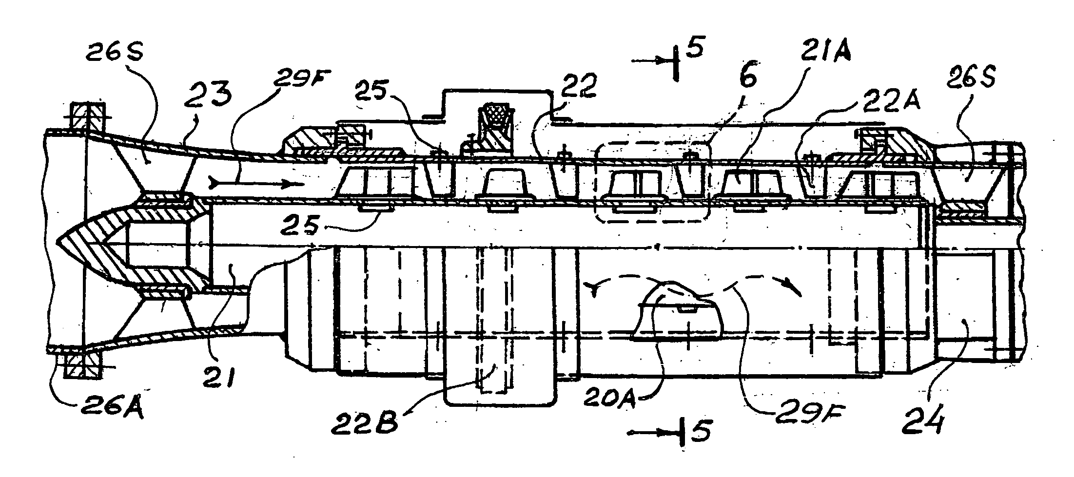
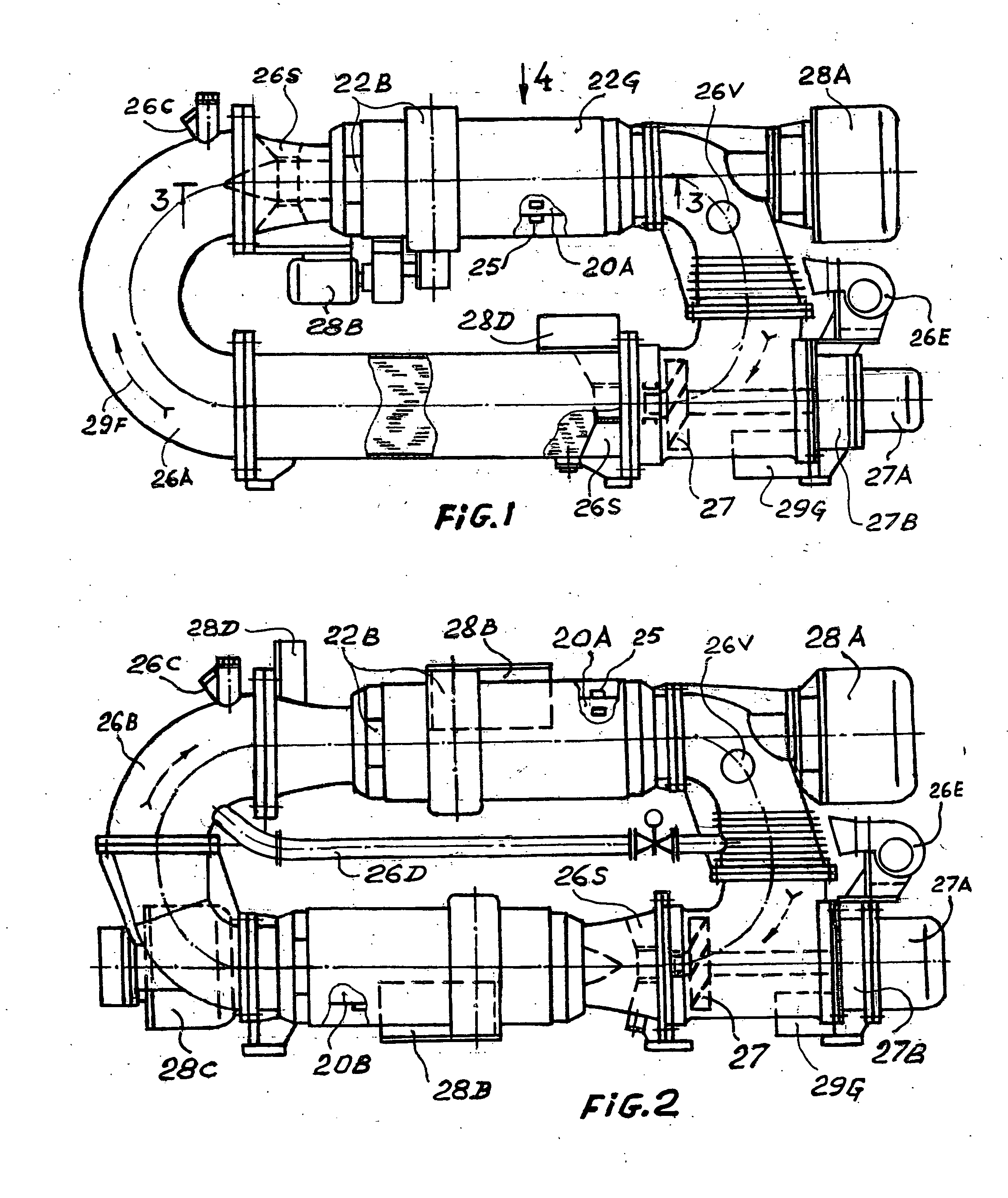
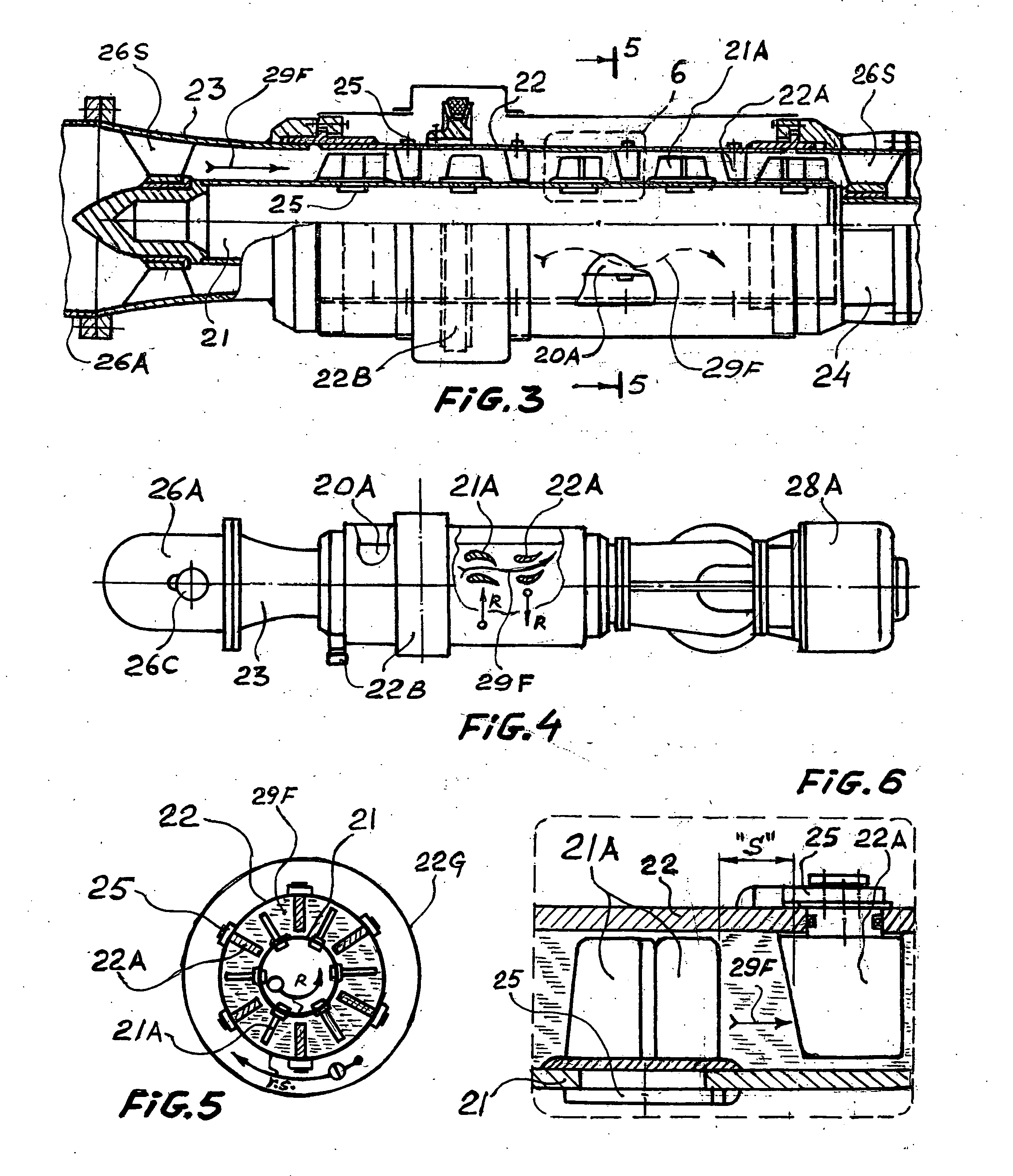
[0059] The FIGS. 1, 2, 3, 4, 5, 6 show the preferred embodiments and arrangements of the present proposal its units, subunits, and their interactions.

[0060] A hydrodynamic closed loop turobset-selfbooster, its turbotechnology as illustrated in FIG. 1 includes at least an axial bispindle hydroturbine 20A installed into closed loop tubular liquid tunnel 26A with an axial-flow propeller pump 27. The definite amount of operative liquid which is completely filled into said tunnel is preferably a high density operative liquid under definite controlled static pressure. The hydroturbine 20A being bispindle drive two electric generators 28A and 28B by each spindle and could drive any other receivers of turbine's power in other designs. The turboset has a tunnel air-cooler 26E placed near cooling fins of the tunnel 26A, a kit of needed hydraulic and electric meters and general control panel 29G.

[0061] Another, a cascade embodiment of this proposal is hown in FIG. 2 where two axial bispindle...


PUM


Abstract

The Hydrodynamic closed loop turboset-selfbooster comprises one or more axial bispindle multistage hydrolic turbines (20A, 20B) placed into a common closed-loop tubular tunnel (26B) with an axial-flow propeller pump (27) which works in self-series, as a self-booster impelling high potential operating liquid, filled inside the tunnel. The natural accumulative turbotechnology provides high energy ratio and thus profound general efficiency. The proposal leads to: (a) wide range of universal power units including perfect hydraulic turbines and effective motors for vehicles and other means instead of ineffective heat engines, (b) prospective gradual elimination of fuels for many kinds of power units, (c) ecological purity without any harm emissions and pollutions, (d) multiple high efficient design versions of different power levels, various performances and diverse purposes.

Description

CROSS-REFERENCE TO RELATED APPLICATIONS [0001] This application claims the benefit of Provisional Patent Application No. 60 / 709,444 filed Aug. 19, 2005 by present inventor.FEDERALLY SPONSORED RESEARCH [0002] Not applicable. SEQUENCE LISTING OR PROGRAM [0003] Not applicable. BACKGROUND OF THE INVENTION Technical Field; Prior Art [0004] This proposal relates to hydrodynamic and electro-mechanical structures which provide effective accumulating energy transfer especially to universal motors and turbines. Conventionally there are known heat engines and turbines widely used in motor vehicles and other moving and static power sets. A common principal defect of most of them is their low about 40% total efficiency. Their imperfect general technology leads to power wasting, large and costly fuel consumption, and non-prospective burning out their combustibles. [0005] These conventional heat engines and some turbines are ineffective because of high energy dissipating. They pollute the nature a...

Claims


Application Information

Patent Timeline
Patent Type & Authority Applications(United States)
IPC IPC(8): F01D1/02
CPCF01D1/00F02C1/08F03B17/005F03G7/10F05B2220/32
Inventor LAZAR, BERELI M.
Owner LAZAR BERELI M
Why Eureka
Try Eureka